USB-2408 Series 24-Bit Multifunction Temperature and Voltage Devices USB-2408 USB-2408-2AO User's Guide Document Revision 3 June 2014 © Copyright 2014
Your new Measurement Computing product comes with a fantastic extra – Management committed to your satisfaction! Refer to www.mccdaq.com/execteam.html for the names, titles, and contact information of each key executive at Measurement Computing. Thank you for choosing a Measurement Computing product – and congratulations! You own the finest, and you can now enjoy the protection of the most comprehensive warranties and unmatched phone tech support.
Table of Contents Preface About this User's Guide ....................................................................................................................... 5 What you will learn from this user's guide ......................................................................................................... 5 Conventions in this user's guide .........................................................................................................................
USB-2408 Series User's Guide Analog voltage output (USB-2408-2AO only) ................................................................................................. 26 Analog input/output calibration ........................................................................................................................ 27 Digital input/output........................................................................................................................................... 28 Counter ............
Preface About this User's Guide What you will learn from this user's guide This user's guide describes the Measurement Computing USB-2408 Series data acquisition devices and lists device specifications. Conventions in this user's guide For more information about … Text presented in a box signifies additional information and helpful hints related to the subject matter you are reading.
Chapter 1 Introducing the USB-2408 Series Overview: USB-2408 Series features The USB-2408, USB-2408-2AO includes the following devices: USB-2408 USB-2408-2AO These devices are USB 2.
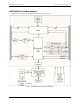
USB-2408 Series User's Guide Introducing the USB-2408 Series USB-2408 Series block diagram USB-2408 Series functions are illustrated in the block diagram shown here. Figure 1.
Chapter 2 Installing a USB-2408 Series Device What comes with your shipment? As you unpack your USB-2408 Series device, verify that the following components are included. Hardware USB-2408 Series device (USB-2408 or USB-2408-2AO) USB cable (2-meter length) Documentation MCC DAQ Quick Start Guide The Quick Start Guide booklet provides an overview of the MCC DAQ software you received with the device, and includes information about installing the software.
USB-2408 Series User's Guide Installing a USB-2408 Series Device Caution! Do not disconnect any device from the USB bus while the computer is communicating with the USB-2408 Series device, or you may lose data and/or your ability to communicate with the device. If the Status LED turns off If the Status LED turns on but then turns off, the computer has lost communication with the USB-2408 Series device. To restore communication, disconnect the USB cable from the computer and then reconnect it.
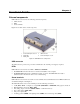
Chapter 3 Functional Details External components USB-2408 Series devices have the following external components: USB connector LEDs Screw terminals Figure 2 shows the location of each component. 1 2 3 Screw terminal pins 23 to 44 Status LED Activity LED 4 5 USB Connector Screw terminal pins 1 to 22 Figure 2. USB-2408 Series components USB connector The USB connector provides 5 V power and communication. No external power supply is required.
USB-2408 Series User's Guide Functional Details Figure 3. SE mode pinout * These pins are labeled NC (no connection) on the USB-2408. Figure 4. DIFF mode pinout * These pins are labeled NC (no connection) on the USB-2408.
USB-2408 Series User's Guide Functional Details Signal connections Input isolation USB-2408 Series devices are isolated data acquisition devices. The analog I/O, digital I/O, counters, and all the digital control/timing are referenced to an isolated ground as shown in the figure below. This ground is physically and electrically separate from the ground used by the circuit connected to the system bus interface.
USB-2408 Series User's Guide Functional Details Analog input mode You can configure the analog inputs for SE or DIFF mode. The input voltage range is software selectable for ±10 V, ±5 V, ±2.5 V, ±1.25 V, ±0.625 V, ±0.312 V, ±0.156 V, or ±0.078 V. With SE mode, connect up to 16 inputs to screw terminals CH0 to CH15. SE mode requires two wires: Connect one wire to the signal you want to measure (CHx). Connect one wire to the analog ground reference ( AGND).
USB-2408 Series User's Guide Functional Details An example of a 12-element list is shown in the table below. Sample channel gain queue list Element Channel Range 0 1 2 3 4 5 6 7 8 9 10 11 CH0 CH1 CH0 CH4 CH8 CH0 CH1 CH7 CH0 CH15 CH9 CH10 BIP10V BIP5V BIP2Pt5VOLTS BIP2Pt5VOLTS BIP2Pt5VOLTS BIP5V BIP1Pt25VOLTS BIP5V BIP1Pt25VOLTS BIP10V BIP1Pt25VOLTS BIP2Pt5VOLTS Carefully match the gain to the expected voltage range on the associated channel or an over range condition may occur.
USB-2408 Series User's Guide Functional Details Figure 7 shows a typical TC connection. Figure 7. DIFF TC connection example Noise filtering, data rate and throughput rate Although the USB-2408 Series A/D converter has a maximum data rate of 3,750 samples per second, the actual throughput rate you observe for voltage and temperature data is determined by these formulas.
USB-2408 Series User's Guide Functional Details At higher data rates, higher-frequency noise sources are not averaged out and begin to be troublesome. These noise sources include the noise inherent in the A/D converter itself, which is not reducible. Since TCs can pick up noise in your environment, select a data rate based on the primary noise frequency. For example, to reduce the effect of 60 Hz noise, select a data rate of 60 (or a supported submultiple of 60, such as 10 or 5).
USB-2408 Series User's Guide Functional Details Figure 10 shows a typical DIO connection. Figure 10. Digital output connection example The figure represents connections for one channel. The other seven channels are connected in the same manner. The maximum sink current is 150 mA per 8-channel bank, or if all eight channels are used, 18 mA (maximum) per channel.
USB-2408 Series User's Guide Functional Details Figure 11. Location of J6 jumper Figure 12 shows the jumper configured for pull-up and pull-down. Figure 12. J6 jumper configurations 6. Replace the top section of the case, and fasten it to the bottom section with the four screws. Replace the rubber feet.
USB-2408 Series User's Guide Functional Details External pull-up/pull-down capability You can also place an external pull-up resistor on any of the DIO bits, which enables you to pull the DIO bit up to a voltage that exceeds the internal +5 V pull-up voltage. When using external pull-up resistors, be aware of the following: You should either remove the J6 jumper, or store it by attaching it to one of the three pins.
USB-2408 Series User's Guide Functional Details Mechanical drawings Figure 14.
Chapter 4 Specifications All specifications are subject to change without notice. Typical for 25 °C unless otherwise specified. All specifications apply to all temperature and voltage input channels unless otherwise specified. Specifications in italic text are guaranteed by design. Analog input Table 1.
USB-2408 Series User's Guide Specifications Note 1: Placing a notch of the A/D digital filter at 60 Hz (setting A/D data rate = 60 S/s, 10 S/s, 5 S/s or 2.5 S/s) further improves the common mode rejection of this frequency. Channel configurations When any item is changed, the firmware stores channel configurations in the EEPROM of the isolated microcontroller. An external application issues commands over the USB to make changes, and the configuration is made non-volatile through the use of the EEPROM.
USB-2408 Series User's Guide Specifications Table 4. Thermocouple accuracy specifications, including CJC measurement error. All specifications are (±). Thermocouple J K N R S B E T Sensor temperature range Accuracy error, maximum Accuracy error, typical –210 °C 0 °C 1200 °C –210 °C 0 °C 1372 °C –200 °C 0 °C 1300 °C –50 °C 250 °C 1768 °C –50 °C 250 °C 1768 °C 250 °C 700 °C 1820 °C –200 °C 0 °C 1000 °C –200 °C 0 °C 400 °C 2.572 °C 0.935 °C 1.869 °C 2.917 °C 1.017 °C 2.478 °C 3.480°C 1.201 °C 1.
USB-2408 Series User's Guide Specifications Input bandwidth Table 6. input bandwidth A/D data rate –3 db Bandwidth (Hz) 3750 S/s 2000 S/s 1000 S/s 500 S/s 100 S/s 60 S/s 50 S/s 25 S/s 10 S/s 5 S/s 2.5 S/s 1615 878 441 221 44.2 26.5 22.1 11.1 4.42 2.21 1.1 Noise performance For the peak-to-peak noise distribution test, a differential input channel is connected to AGND at the input terminal block, and 50,000 samples are acquired at the maximum rate available at each setting. Table 7.
USB-2408 Series User's Guide Specifications Table 9. Noise-free resolution specifications (bits) A/D data rate Range 3750 S/s 2000 S/s 1000 S/s 500 S/s 100 S/s 60 S/s 50 S/s 25 S/s 10 S/s 5 S/s 2.5 S/s ±10 V ±5 V ±2.5 V ±1.25 V ±0.625 V ±0.3125 V ±0.15625 V ±0.078125 V 17.2 17.4 17.2 17.0 16.0 15.3 14.5 14.5 17.6 17.6 17.4 17.1 16.2 15.3 14.1 14.3 18.1 18.1 18.1 17.4 17.1 16.2 15.3 15.0 18.7 18.5 18.4 18.0 17.3 16.4 15.5 15.4 19.3 19.2 19.3 18.8 17.8 17.0 15.7 16.1 19.3 19.4 19.4 18.
USB-2408 Series User's Guide Specifications The multiple-channel throughput rate is calculated using this formula: Maximum throughput = , where n is the number of channels Table 12. Multiple-channel throughput rate specifications (Hz) Number of input channels 3750 S/s 2000 S/s 1000 S/s 500 S/s 100 S/s 60 S/s 50 S/s 25 S/s 10 S/s 5 S/s 2.5 S/s 1 2 3 4 5 6 7 8 9 10 11 12 13 14 15 16 1102.94 551.47 367.65 275.74 220.59 183.82 157.56 137.87 122.55 110.29 100.27 91.91 84.84 78.78 73.53 68.
USB-2408 Series User's Guide Parameter Specifications Conditions Specifications Power on and reset state Output noise Settling time Slew rate Throughput DACs cleared to zero-scale: 0 V, ±50 mV 60 µVrms (BW=1.5 KHz) 75 µS 1.0 V/µs 1000 S/s max, system-dependent, 0.01 S/s min 1000 S/s / #ch max, systemdependent, 0.01 S/s min To rated accuracy, 10 V step Single-channel Multi-channel Table 14. Calibrated absolute accuracy specifications Range Accuracy (±LSB) ±10 V 16.0 Table 15.
USB-2408 Series User's Guide Specifications Digital input/output Table 18. Digital input specifications Parameter Specifications Number of I/O Configuration 8 channels Each DIO bit can be independently read from (DIN) or written to (DOUT). The DIN bits can be read at any time whether the DOUT is active or tri-stated.
USB-2408 Series User's Guide Specifications Counter Table 20. CTR specifications Parameter Conditions Specification Pin name Number of channels Resolution Counter type Input type Input source Counter read/writes rates (software paced) Input characteristics CTR0, CTR1 2 channels 32-bits Event counter Schmitt trigger, rising edge triggered CTR0 (pin 44) CTR1 (pin 42) System dependent, 500 reads per second. System dependent, 500 writes per second.
USB-2408 Series User's Guide Specifications Power Table 23. Power specifications Parameter Conditions Specification Supply current (Note 8) Voltage supervisor limits Quiescent current 4.5 V > Vext or Vext > 5.5 V 4.5 V < Vext < 5.5 V Available at terminal block pin 40 Available at terminal block pin 40 Measurement system to PC 275 mA PWR LED = Off; (power fault) PWR LED = On 4.75 V min to 5.
USB-2408 Series User's Guide Specifications Screw terminal pinout Table 28.
USB-2408 Series User's Guide Specifications Table 29.
Declaration of Conformity Manufacturer: Address: Category: Measurement Computing Corporation 10 Commerce Way Suite 1008 Norton, MA 02766 USA Electrical equipment for measurement, control and laboratory use.
Measurement Computing Corporation 10 Commerce Way Suite 1008 Norton, Massachusetts 02766 (508) 946-5100 Fax: (508) 946-9500 E-mail: info@mccdaq.com www.mccdaq.