
User Manual


USB-201 User's Guide Functional Details
9
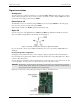
Screw terminals
The screw terminals provide the following connections:
Eight single-ended analog inputs (CH0 to CH7)
Eight digital I/O (DI00 to DI07)
External pacer clock input (AICKI)
External pacer clock output (AICKO)
Digital trigger input (TRIG)
Counter input (CTR)
User voltage output (+VO)
Analog ground reference (AGND) and digital ground reference (GND)
Figure 3. USB-201 pinout
USB connector
The USB connector provides +5 V power and communication. No external power supply is required.
LED indicators
The device has two LED indicators – Status and Activity.
The Status LED turns on when the device is detected and installed on the computer.
The Activity LED blinks when data is transferred, and is off otherwise.
Refer to Figure 2 on page 8 for the location of these LEDs.