
User Manual


USB-201 User's Guide Functional Details
10
Signal connections
Analog input
You can connect up to 8 single-ended inputs to screw terminals CH0 to CH7. The input voltage range is ±10 V.
Single-ended mode requires two wires; connect one wire to the signal you want to measure (CHx), and connect
a second wire to the analog ground reference (AGND).
External pacer I/O
The USB-201 provides one external clock input (AICKI) and one clock output (AICKO) for the analog input
pacer. You can connect an external clock signal to AICKI.
When using the internal clock, AICKO outputs the ADC sample clock.
Digital I/O
You can connect up to eight digital I/O lines to DIO0 through DIO7. The digital I/O terminals can detect the
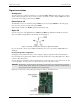
state of any TTL-level input. Refer to the schematic shown in Figure 4.
Figure 4. Schematic showing switch detection by digital channel DIO0
If you set the switch to the +5 V input, DIO0 reads TRUE (1). If you move the switch to GND, DIO0 reads
FALSE (0).
Internal pull-up/down configuration
The digital port has 47 kΩ resistors that you can configure as pull-up or pull-down with an internal jumper.
Unconnected inputs are pulled low by default to 0 V through 47 kΩ resistors. The pull-up/pull-down voltage is
common to all 47 kΩ resistors.
You can change the configuration with an internal jumper. You must remove the cover from the device in order
to access the jumper. To remove the cover, unscrew the four screws on the device bottom.
Caution! The discharge of static electricity can damage some electronic components. Before removing the
device from its housing, either ground yourself using a wrist strap or touch the computer chassis or
other grounded object to eliminate any stored static charge.
Figure 5 shows the location of the pull-up/down jumper in relation to the USB connector.
Figure 5. Pull-up/down jumper location