USB-204 Analog and Digital I/O User's Guide Document Revision 6 November 2014 © Copyright 2014
Your new Measurement Computing product comes with a fantastic extra — Management committed to your satisfaction! Thank you for choosing a Measurement Computing product—and congratulations! You own the finest, and you can now enjoy the protection of the most comprehensive warranties and unmatched phone tech support. It’s the embodiment of our mission: To provide data acquisition hardware and software that will save time and save money.
Table of Contents Preface About this User's Guide ....................................................................................................................... 5 What you will learn from this user's guide ......................................................................................................... 5 Conventions in this user's guide .........................................................................................................................
USB-204 User's Guide Mechanical ....................................................................................................................................................... 18 Screw terminal connector ................................................................................................................................. 18 Declaration of Conformity ..................................................................................................................19 HM USB-204.
Preface About this User's Guide What you will learn from this user's guide This user's guide describes the Measurement Computing USB-204 data acquisition device and lists device specifications. Conventions in this user's guide For more information Text presented in a box signifies additional information related to the subject matter. Caution! Shaded caution statements present information to help you avoid injuring yourself and others, damaging your hardware, or losing your data.
Chapter 1 Introducing the USB-204 The USB-204 is a USB 2.
Chapter 2 Installing the USB-204 Unpacking As with any electronic device, you should take care while handling to avoid damage from static electricity. Before removing the device from its packaging, ground yourself using a wrist strap or by simply touching the computer chassis or other grounded object to eliminate any stored static charge. Contact us immediately if any components are missing or damaged.
Chapter 3 Functional Details Analog input acquisition modes The USB-204 can acquire analog input data in two different modes – software paced and hardware paced. Software paced mode You can acquire one analog sample at a time in software paced mode. You initiate the A/D conversion with a software command. The analog value is converted to digital and returned to the computer. You can repeat this procedure until you have the total number of samples that you want.
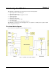
USB-204 User's Guide Functional Details Screw terminals The screw terminals provide the following connections: Eight single-ended analog inputs (CH0 to CH7) Eight digital I/O (DI00 to DI07) External pacer clock input (AICKI) External pacer clock output (AICKO) Digital trigger input (TRIG) Counter input (CTR) User voltage output (+VO) Analog ground reference (AGND) and digital ground reference (GND) Figure 3.
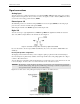
USB-204 User's Guide Functional Details Signal connections Analog input You can connect up to 8 single-ended inputs to screw terminals CH0 to CH7. The input voltage range is ±10 V. Single-ended mode requires two wires; connect one wire to the signal you want to measure (CHx), and connect a second wire to the analog ground reference (AGND). External pacer I/O The USB-204 provides one external clock input ( AICKI) and one clock output ( AICKO) for the analog input pacer.
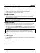
USB-204 User's Guide Functional Details Figure 6 shows the jumper configured for pull-down. Figure 6. Pull-down jumper Configure the jumper for pull-up to pull the digital inputs high (+5V). Proper LED alignment When placing the circuit board within the housing, align the board LEDs with the top of the housing before attaching the housing bottom. Trigger input The TRIG terminal is an external digital trigger input. The trigger mode is software-selectable for edge- or level-sensitive.
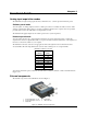
USB-204 User's Guide Functional Details Mechanical drawings Figure 7.
USB-204 User's Guide Functional Details Figure 8.
Chapter 4 Specifications All specifications are subject to change without notice. Typical for 25 °C unless otherwise specified. Specifications in italic text are guaranteed by design. Analog input Table 1.
USB-204 User's Guide Specifications Noise performance For the peak to peak noise distribution test, the input channel is connected to AGND at the input terminal block, and 12,000 samples are acquired at the maximum throughput. Table 3. Noise performance specifications Range Counts LSBrms ±10 V 5 0.76 Analog input calibration Table 4.
USB-204 User's Guide Specifications External digital trigger Table 6. External digital trigger specifications Parameter Specification Trigger source Trigger mode TRIG input Software configurable for edge or level sensitive, rising or falling edge, high or low level. Power on default is edge sensitive, rising edge. 1 µs + 1 pacer clock cycle max 125 ns min Schmitt trigger, 47 kΩ pull-down to ground 1.01 V typ 0.6 V min 1.5 V max 2.43 V typ 1.9 V min 3.1 V max 1.42 V typ 1.0 V min 2.0 V max 5.
USB-204 User's Guide Specifications Counter Table 8. CTR specifications Parameter Specification Pin name Number of channels Resolution Counter type Input type Counter read/write rates (software paced) CTR 1 channel 32-bit Event counter Schmitt trigger, 47 kΩ pull-down to ground 33 to 4,000 reads/writes per second typ, system dependent Schmitt trigger hysteresis 1.01 V typ 0.6 V min 1.5 V max 2.43 V typ 1.9 V min 3.1 V max 1.42 V typ 1.0 V min 2.0 V max 5.5 V absolute max –0.
USB-204 User's Guide Specifications USB specifications Table 11. USB specifications Parameter Specification USB device type Device compatibility USB cable type USB 2.0 (full-speed) USB 1.1, USB 2.0 A-B cable, UL type AWM 2725 or equivalent. (minimum 24 AWG VBUS/GND, minimum 28 AWG D+/D–) 3 m (9.84 ft) max USB cable length Environmental Table 12.
Declaration of Conformity Manufacturer: Address: Category: Measurement Computing Corporation 10 Commerce Way Suite 1008 Norton, MA 02766 USA Electrical equipment for measurement, control and laboratory use.
Measurement Computing Corporation 10 Commerce Way Suite 1008 Norton, Massachusetts 02766 (508) 946-5100 Fax: (508) 946-9500 E-mail: info@mccdaq.com www.mccdaq.