
User Manual


USB-1208LS User's Guide Specifications
19
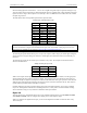
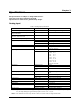
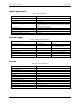
Table 2. Accuracy, differential mode
Range Accuracy (LSB)
±20 V
5.1
±10 V
6.1
±5 V
8.1
±4 V
9.1
±2.5 V
12.1
±2 V
14.1
±1.25 V
20.1
±1 V
24.1
Table 3. Accuracy, single-ended mode
Range Accuracy (LSB)
±10 V
4.0
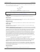
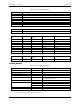
Table 4. Accuracy components, differential mode – all values are (±)
Range % of Reading Gain Error at FS
(mV)
Offset (mV) Accuracy at FS (mV)
±20 V
0.2
40
9.766
49.766
±10 V
0.2
20
9.766
29.766
±5 V
0.2
10
9.766
19.766
±4 V
0.2
8
9.766
17.766
±2.5 V
0.2
5
9.766
14.766
±2 V
0.2
4
9.766
13.766
±1.25 V
0.2
2.5
9.766
12.266
±1 V
0.2
2
9.766
11.766
Table 5. Accuracy components, single-ended mode – all values are (±)
Range % of Reading Gain Error at FS
(mV)
Offset (mV) Accuracy at FS (mV)
±10 V 0.2 20 19.531 39.531
Analog output
Table 6. Analog output specifications
Parameter Conditions Specification
D/A converter type
PWM
Resolution
10-bits, 1 in 1024
Maximum output range
0 V to 5 V
Number of channels
2
Throughput Software paced 100 S/s single-channel mode
50 S/s dual-channel mode
Power on and reset voltage
Initializes to 000h code
Maximum voltage (Note 3)
No load
Vs
1 mA load
0.99 * Vs
5 mA load
0.98 * Vs
Output current drive
Each D/A OUT
30 mA
Slew rate
0.14 V/ms typ
Note 3: Vs is the USB bus +5V power. The maximum analog output voltage is equal to Vs at no-load. V is
system-dependent and may be less than 5 volts.