USB-1208LS Analog and Digital I/O User's Guide Document Revision 4 June 2015 © Copyright 2015
Your new Measurement Computing product comes with a fantastic extra — Management committed to your satisfaction! Thank you for choosing a Measurement Computing product—and congratulations! You own the finest, and you can now enjoy the protection of the most comprehensive warranties and unmatched phone tech support. It’s the embodiment of our mission: To provide data acquisition hardware and software that will save time and save money.
Table of Contents Preface About this User's Guide ....................................................................................................................... 5 Conventions in this user's guide ......................................................................................................................... 5 Where to find more information .........................................................................................................................
USB-1208LS User's Guide Declaration of Conformity ..................................................................................................................
Preface About this User's Guide This user's guide describes the Measurement Computing USB-1208LS data acquisition device and lists device specifications. Conventions in this user's guide For more information Text presented in a box signifies additional information related to the subject matter. Caution! Shaded caution statements present information to help you avoid injuring yourself and others, damaging your hardware, or losing your data.
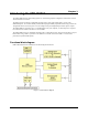
Chapter 1 Introducing the USB-1208LS The USB-1208LS features eight analog inputs, two 10-bit analog outputs, 16 digital I/O connections, and one 32-bit external event counter. The analog inputs are software configurable for either eight 11-bit single-ended inputs, or four 12-bit differential inputs. An on-board industry standard 82C55 programmable peripheral interface chip provides the 16 digital I/O lines in two 8-bit ports. You can configure each port independently for either input or output.
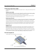
Chapter 2 Installing the USB-1208LS Unpacking As with any electronic device, you should take care while handling to avoid damage from static electricity. Before removing the device from its packaging, ground yourself using a wrist strap or by simply touching the computer chassis or other grounded object to eliminate any stored static charge. Contact us immediately if any components are missing or damaged.
Chapter 2 Functional Details Analog input acquisition modes The USB-1208LS can acquire analog input data in three different modes – software paced, hardware paced, and BURSTIO. Software paced mode You acquire one analog sample at a time in software paced mode. You initiate the A/D conversion by calling a software command. The analog value is converted to digital and returned to the computer. You can repeat this procedure until you have the total number of samples that you want from one channel.
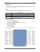
USB-1208LS User's Guide Functional Details USB connector The USB connector is on the right side of the USB-1208LS housing. This connector provides +5V power and communication. The voltage supplied through the USB connector is system-dependent, and may be less than 5V. No external power supply is required. LED The LED on the front of the housing indicates the communication status of the USB-1208LS. It uses up to 5 mA of current and cannot be disabled. The table below defines the function of the LED.
USB-1208LS User's Guide Functional Details The single-ended mode pinout is shown in Figure 4. Figure 4. Single-ended mode pinout Signal connections Analog inputs You can connect up to eight analog input connections to the screw terminal containing pins 1 to 20 (CH0 IN through CH7 IN). You can configure the analog input channels as eight single-ended channels or four differential channels. When configured for differential mode, each analog input has 12-bit resolution.
USB-1208LS User's Guide Functional Details In differential mode, the following two requirements must be met for linear operation: Any analog input must remain in the −10V to +20V range with respect to ground at all times. The maximum differential voltage on any given analog input pair must remain within the selected voltage range. The input [common-mode voltage + signal] of the differential channel must be in the −10 V to +20 V range in order to yield a useful result.
USB-1208LS User's Guide Functional Details Since the analog inputs are restricted to a −10 V to +20 V signal swing with respect to ground, all ranges except ±20V can realize a linear output for any differential signal with zero common mode voltage and full scale signal inputs. The ±20 V range is the exception. You cannot put −20 V on CHHI and 0 V on CHLO since this violates the input range criteria. The table below shows some possible inputs and the expected results.
USB-1208LS User's Guide Functional Details Refer to the schematic shown in Figure 8. If the switch is set to the +5 V input, Port A0 reads TRUE (1). If you move the switch to GND, Port A0 reads FALSE. Figure 8. Schematic showing switch detection by digital channel Port A0 For more information on digital signal connections For more information on digital signal connections and digital I/O techniques, refer to the Guide to DAQ Signal Connections (available on our web site at www.mccdaq.
USB-1208LS User's Guide Functional Details Accuracy The overall accuracy of any instrument is limited by the error components within the system. Quite often, resolution is incorrectly used to quantify the performance of a measurement product. While "12-bits" or "1 part in 4096" does indicate what can be resolved, it provides little insight into the quality of an absolute measurement. Accuracy specifications describe the actual results that can be realized with a measurement device.
USB-1208LS User's Guide Functional Details The accuracy plots in Figure 10 are drawn for clarity and are not drawn to scale. Figure 10. ADC transfer function with offset error Gain error is a change in the slope of the transfer function from the ideal, and is typically expressed as a percentage of full-scale. Figure 11 shows the USB-1208LS transfer function with gain error. Gain error is easily converted to voltage by multiplying the full-scale (FS) input by the error.
USB-1208LS User's Guide Functional Details Combining these two error sources in Figure 12, we have a plot of the error band of the USB-1208LS for the ±10 V range. This is a graphical version of the typical accuracy specification of the product. The accuracy plots in Figure 12 are drawn for clarity and are not drawn to scale. Figure 12.
USB-1208LS User's Guide Functional Details Mechanical drawings Figure 13.
Chapter 3 Specifications All specifications are subject to change without notice. Typical for 25°C unless otherwise specified. Specifications in italic text are guaranteed by design. Analog input Table 1.
USB-1208LS User's Guide Specifications Table 2. Accuracy, differential mode Range Accuracy (LSB) ±20 V ±10 V ±5 V ±4 V ±2.5 V ±2 V ±1.25 V ±1 V 5.1 6.1 8.1 9.1 12.1 14.1 20.1 24.1 Table 3. Accuracy, single-ended mode Range Accuracy (LSB) ±10 V 4.0 Table 4. Accuracy components, differential mode – all values are (±) Range % of Reading Gain Error at FS (mV) Offset (mV) Accuracy at FS (mV) ±20 V ±10 V ±5 V ±4 V ±2.5 V ±2 V ±1.25 V ±1 V 0.2 0.2 0.2 0.2 0.2 0.2 0.2 0.2 40 20 10 8 5 4 2.5 2 9.
USB-1208LS User's Guide Specifications Digital input/output Table 7. DIO specifications Parameter Specification Digital type Number of I/O Configuration Pull up/pull-down configuration 82C55 16 (Port A0 through A7, Port B0 through B7 2 banks of 8 All pins pulled up to Vs through 47 kΩ resistors (default). Positions available for pull down to ground. Hardware-selectable through 0 Ω resistors as a factory option. 2.0 V min, 5.5 V absolute max 0.8 V max, –0.5 V absolute min 3.0 V min 0.
USB-1208LS User's Guide Specifications Non-volatile memory Table 10. Memory specifications Parameter Specification Memory size Memory configuration 8192 bytes Address Range Access Description 0x0000 – 0x17FF 0x1800 – 0x1EFF 0x1F00 – 0x1FEF 0x1FF0 – 0x1FFF Read/write Read/write Read/write Read/write A/D data (4K samples) User data area Calibration data System data Power Table 11.
USB-1208LS User's Guide Specifications Mechanical Table 14. Mechanical specifications Parameter Specification Dimensions (L × W × H) USB cable length User connection length 79 × 82 × 27 mm (3.10 × 3.20 × 1.05 in.) 3 m (9.84 ft) max 3 m (9.
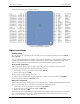
USB-1208LS User's Guide Specifications 8-channel single-ended mode Pin 1 2 3 4 5 6 7 8 9 10 11 12 13 14 15 16 17 18 19 20 Signal Name CH0 IN CH1 IN GND CH2 IN CH3 IN GND CH4 IN CH5 IN GND CH6 IN CH7 IN GND D/A OUT 0 D/A OUT 1 GND CAL GND TRIG_IN GND CTR Pin 21 22 23 24 25 26 27 28 29 30 31 32 33 34 35 36 37 38 39 40 23 Signal Name Port A0 Port A1 Port A2 Port A3 Port A4 Port A5 Port A6 Port A7 GND PC+5V GND Port B0 Port B1 Port B2 Port B3 Port B4 Port B5 Port B6 Port B7 GND
Declaration of Conformity Manufacturer: Address: Category: Measurement Computing Corporation 10 Commerce Way Suite 1008 Norton, MA 02766 USA Electrical equipment for measurement, control and laboratory use.
Measurement Computing Corporation 10 Commerce Way Suite 1008 Norton, Massachusetts 02766 (508) 946-5100 Fax: (508) 946-9500 E-mail: info@mccdaq.com www.mccdaq.