
User Manual

USB-1208FS-Plus User's Guide Functional Details
9
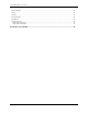
External components
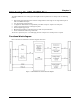
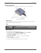
The external components – screw terminal banks, LED, and USB connector –are shown in Figure 2.
1
Screw terminal pins 21 to 40
3
Screw terminal pins 1 to 20
2
LED
4
USB connector
Figure 2. External components
USB connector
Receives the supplied USB cable. When connected to a computer or USB hub, the cable provides power and
communication. No external power supply is required.
LED
The following table lists the behavior of the device LED.
LED state Indication
Steady green
The device is connected to a computer or external USB hub.
Blinks continuously
Data is being transferred.
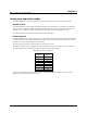
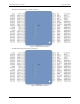
Screw terminals
The screw terminals provide the following connections:
Eight analog input connections (
CH0 IN to CH7 IN, CH0 IN HI/LO through CH3 IN HI/LO)
Two analog output connections (
D/A OUT 0 to D/A OUT 1)
16 digital I/O connections (
PortA0 to Port A7, and Port B0 to Port B7)
External trigger input (
TRIG_IN)
External counter input (
CTR)
Bidirectional terminal for external clocking or multi-unit synchronization (
SYNC)
Power output (
+VO)
Analog ground (
AGND) and ground (GND)
Use 16 AWG to 30 AWG wire when making connections to the screw terminals.