
User Manual

USB-1208FS-Plus User's Guide Functional Details
11
Signal connections
Analog input
You can connect up to eight analog input connections to the screw terminal bank containing pins 1 to 20.
You can configure the analog input channels as eight single-ended channels (
CH0 IN through CH7 IN) or four
differential channels (
CH0 IN HI/LO through CH3 IN HI/LO). When configured for differential mode, each
analog input has 12-bit resolution. When configured for single-ended mode, each analog input has 11-bit
resolution, due to restrictions imposed by the A/D converter.
Single-ended configuration
When configured for single-ended input mode, the input signal is referenced to signal ground (GND) and
delivered through two wires:
Connect the wire carrying the signal to be measured to
CH# IN.
Connect the second wire to
AGND.
The input range for single-ended mode is ±10 V. The single-ended mode pinout is shown in Figure 3 on page
10.
Differential configuration
When configured for differential input mode, the input signal is measured with respect to the low input and
delivered through three wires:
Connect the wire carrying the signal to be measured to
CH# IN HI.
Connect the wire carrying the reference signal to
CH# IN LO.
Connect the third wire to
GND.
The differential mode pinout is shown in Figure 4 on page 10.
Note: To perform a single-ended measurement using differential channels, connect the signal to CH# IN HI and
ground the associated
CH# IN LO input.
A low-noise precision programmable gain amplifier (PGA) is available on differential channels to provide gains
of up to 20 and a dynamic range of up to 12-bits. Differential mode input voltage ranges are ±20 V, ±10 V,
±5 V, ±4 V, ±2.5 V, ±2.0 V, ±1.25 V, and ±1.0 V.
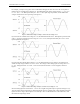
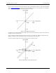
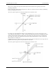
In differential mode, the following two requirements must be met for linear operation:
Any analog input must remain in the −10V to +20V range with respect to ground at all times.
The maximum differential voltage on any given analog input pair must remain within the selected voltage
range.
The input [common-mode voltage + signal] of the differential channel must be in the −10 V to +20 V range in
order to yield a useful result.