USB-1024LS 24-bit Digital I/O Low-speed USB 2.
USB-1024LS USB-based Digital I/O Module User's Guide Document Revision 2, May, 2006 © Copyright 2006, Measurement Computing Corporation
Your new Measurement Computing product comes with a fantastic extra — Management committed to your satisfaction! Thank you for choosing a Measurement Computing product—and congratulations! You own the finest, and you can now enjoy the protection of the most comprehensive warranties and unmatched phone tech support. It’s the embodiment of our mission: To provide data acquisition hardware and software that will save time and save money.
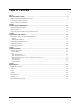
Table of Contents Preface About this User's Guide .......................................................................................................................v What you will learn from this user's guide .........................................................................................................v Conventions in this user's guide .........................................................................................................................v Where to find more information ...
Preface About this User’s Guide What you will learn from this user's guide This user's guide describes the Measurement Computing USB-1024LS data acquisition device and lists device specifications. Conventions in this user's guide For more information Text presented in a box signifies additional information related to the subject matter. Caution! Shaded caution statements present information to help you avoid injuring yourself and others, damaging your hardware, or losing your data.
Introducing the USB-1024LS Chapter 1 This user's guide contains all of the information you need to connect the USB-1024LS measurement and automation device to your computer and to other data acquisition hardware. The USB-DIO24/37 is a USB 1.1 low-speed module supported under popular Microsoft® Windows® operating systems. It is designed for USB 1.1 ports, and was tested for full compatibility with both USB 1.1 and USB 2.0 ports.
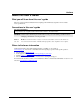
USB-1024LS User's Guide Introducing the USB-1024LS USB-1024LS block diagram USB-1024LS functions are illustrated in the block diagram shown here. USB 1.1 Compliant Interface USB Microcontroller 82C55 DIO Port Port Port Port A B C HI C LO 8 8 4 4 Screw terminal I/O connector 32-bit Event Counter 1 channel 1 Figure 1-2.
USB-1024LS User's Guide Introducing the USB-1024LS Connecting a USB-1024LS to your computer is easy Installing a data acquisition device has never been easier. ! ! ! ! ! ! The USB-1024LS relies upon the Microsoft Human Interface Device (HID) class drivers. The HID class drivers ship with every copy of Windows that is designed to work with USB ports. We use the Microsoft HID because it is a standard, and its performance delivers full control and maximizes data transfer rates for your USB-1024LS.
Chapter 2 Installing the USB-1024LS What comes with your USB-1024LS shipment? The following items are shipped with the USB-1024LS: Hardware ! USB-1024LS ! USB cable (2 meter length) Additional documentation In addition to this hardware user's guide, you should also receive the Quick Start Guide (available in PDF at www.mccdaq.com/PDFs/manuals/DAQ-Software-Quick-Start.pdf).
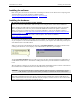
USB-1024LS User's Guide Installing the USB-1024LS Installing the software Refer to the Quick Start Guide for instructions on installing the software on the Measurement Computing Data Acquisition Software CD. This booklet is available in PDF at www.mccdaq.com/PDFs/manuals/DAQ-Software- Quick-Start.pdf. Installing the hardware Be sure you are using the latest system software Before you connect the USB-1024LS, make sure that you are using the latest versions of the USB drivers.
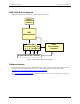
Chapter 3 Functional Details External components The USB-1024LS has the following external components, as shown in Figure 3-1. ! ! ! USB connector LED Screw terminal banks (2) LED Screw terminal Pins 1 to 20 Screw terminal Pins 21 to 40 USB connector / cable Figure 3-1. USB-1024LS external components USB connector The USB connector is on the right side of the USB-1024LS housing. This connector provides +5 V power and communication.
USB-1024LS User's Guide Functional Details Pin 20 Pin 1 Pin 40 Pin 21 Figure 3-2.
Functional Details GND Port B7 Port B6 Port B5 Port B4 Port B3 Port B2 Port B1 Port B0 GND PC+5V GND Port A7 Port A6 Port A5 Port A4 Port A3 Port A2 Port A1 Port A0 40 39 38 37 36 35 34 33 32 31 30 29 28 27 26 25 24 23 22 21 20 19 18 17 16 15 14 13 12 11 10 9 8 7 6 5 4 3 2 1 CTR GND n/c GND n/c GND n/c n/c GND n/c n/c GND Port C7 Port C6 Port C5 Port C4 Port C3 Port C2 Port C1 Port C0 USB-1024LS User's Guide Digital I/O terminals (Port A0 to A7, Port B0 to B7, Port C0 to C7) Connect up to 24 digital I
USB-1024LS User's Guide Functional Details Power terminals The PC +5 V connection (pin 30) is on the bottom screw terminal of the USB-1024LS. Refer to the pinout diagram on page 3-2 for the location of this pin. This terminal draws power from the USB connector. The +5 V screw terminal is a +5 volt output that is supplied by the computer. Caution! The +5 V terminal is an output. Do not connect to an external power supply or you may damage the USB-1024LS and possibly the computer.
Chapter 4 Specifications Typical for 25 °C unless otherwise specified. Specifications in italic text are guaranteed by design. Digital input / output Table 1. Digital I/O specifications Digital type Number of I/O Configuration Pull up/pull-down configuration Input high voltage Input low voltage Output high voltage (IOH = -2.5 mA) Output low voltage (IOH = -2.
USB-1024LS User's Guide Specifications Note 2: Self-powered refers to USB hubs and hosts with a power supply. Bus-powered refers to USB hubs and hosts without their own power supply. Note 3: This refers to the total amount of current that can be sourced from the USB +5V and digital outputs. General Table 4. General specifications Parameter Conditions Specification USB controller clock error 25 °C 0 to 70 °C ±30 ppm max ±50 ppm max USB 1.1 low-speed USB 1.1, USB 2.
USB-1024LS User's Guide Specifications Main connector and pin out Table 7. Connector specifications Connector type Wire gauge range Screw terminal 30-16 AWG Table 8.
Declaration of Conformity Manufacturer: Address: Measurement Computing Corporation 10 Commerce Way Suite 1008 Norton, MA 02766 USA Measurement Computing Corporation declares under sole responsibility that the product USB-1024LS to which this declaration relates is in conformity with the relevant provisions of the following standards or other documents: EU EMC Directive 89/336/EEC: Electromagnetic Compatibility, EN 61326 (1997) Amendment 1 (1998) Emissions: Group 1, Class A ! EN 55011 (1990)/CISPR 11: Ra
Measurement Computing Corporation 10 Commerce Way Suite 1008 Norton, Massachusetts 02766 (508) 946-5100 Fax: (508) 946-9500 E-mail: info@mccdaq.com www.mccdaq.