
Datasheet

ON
ON
Enable
Enable
ON
ON
(For special custom made
RC P-1000 mo dels)
Volta ge of power device can not be a djusted.
Volta ge of power device can be adju sted indep endently by VRs.
1 2
1
1
1
1
2
2
2
2
3
3
3
3
Module A
(12V)
(a)
(b)
(24V )
(66V)
Module B Module C
3 4 5 6 7 8 9
OFF
OFF
Disable
Disable
OFF
OFF
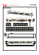
1. Monitoring Input
The diagram be low only shows one set of inpu t / output signals. One RCP-MU can co ntrol and monitor up to 3 units of RCP-1000 power un it.
ON / OFF
PSU ON/OFF
Model
Select
PSU
Output Adjust
+V
V- Trim
-V
SC A / SDL
2. Alarm Signa l Relay Contac t
3. Model Selec t Switch
To get better display resolution, the correct out put voltage of RCP-1 000 that is monitore d should b e chosen. The facto ry original setting is for 48V mo dels.
The output voltage adjustm ent for RC P-1000 u nits can be enabled or disabled for different applica tion needs.
4. Output Volta ge Lock
RCP-1U Address dip switch s etting
RCP -1U
MCU LED Alarm
Rela y
Contact
Displ ay
AC Fail
AC Fail
Voltage
DC Fail
DC Fail
Current
Temp Alarm
Temp Alarm
12V
24V
48V
66V
Temperature
CN500
RCP -MU
Co mmun ic ati on
Function
AC Fail
DC Fail
Temp Alarm
Description
When input AC fail, relay open, LED lig hts
When output DC fail, relay open, LED lights
When temperatur e exceed the limit of temperature, relay open, LED lig hts
1 2 3
(48 V)
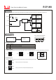
Block Diagram
Typical User Manual
Power Control and Monitor System
R CP -M U
File Name:RCP-M U-SPEC 2011-08-19
ON
1 2 3
OFF