
Data Sheet
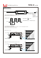


DIMMING OPERATION
◎ Applying additive 0 ~ 10VDC
◎ Applying additive 10V PWM signal (frequency range 100Hz ~ 3KHz):
LED Strips
LED Strips
Vo+
Vo-
DIM+
DIM-
+
+
+
+
-
-
-
-
“DO NOT connect "DIM- to Vo-"
Additive Voltage
DIM+
DIM-
+
-
“DO NOT connect "DIM- to Vo-"
Additive PWM signal
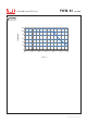
0V 1V 2V 3V 4V 5V 6V 7V 8V 9V 10V
20%
30%
40%
50%
60%
70%
80%
90%
100%
0%
10% 20% 30% 40% 50% 60% 70% 80% 90% 100%
10%
20%
30%
40%
50%
60%
70%
80%
90%
100%
Dimming input: Additive voltage
Duty cycle of additive 10V PWM signal dimming input
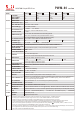
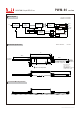
※ Dimming principle for PWM style output
‧Apply one of the three methodologies between DIM+ and DIM-: 0 ~ 10VDC, or 10V PWM signal or resistance.
‧Dimming source current from power supply: 100 A (typ.)μ
ON
OFF
TON
T
Output DC current
Io=0A
Output PWM frequency : 1.47kHz fixed (Typ.)
Duty cycle(%) = ×100%
TON
T
‧Dimming is achieved by varying the duty cycle of the output current.
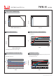
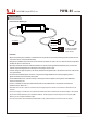
※ 3 in 1 dimming function (for Blank-Type)
60W PWM Output LED Driver
PW M-6 0 ser i es
10%
0%
Duty cycle of output current (%)Duty cycle of output current (%)
UL2464 18AWG×2C(Vo+,Vo-)
UL2464 22AWG×2C(DIM+,DIM-)
Vo+(Red)
DIM+(Blue)*
Vo-(Black)
DIM-(White)* *
SJTW 18AWG×2C
AC/L(Brown)
AC/N(Blue)
Vo+
Vo-
0.6V 1V
0.15%
10%
6% 10%
0.15%
10%
File Name:PWM-60-SPEC 2019-05-10
* DIM+ for Blank-Type
DA+ for DA-type
* *DIM- for Blank-Type
DA- for DA-type
NOTE: DA Type is no distinction
between “+” and “-” poles