
Instruction Manual

9
locking ring
adjustment
screws
viewfinder
eyepiece/focuser
viewfinder
bracket
and dovetail
mount
tripod base with
leg receptacles
leg
attachment
lock
sliding leg
trigger
release
locking latch
and thruster bar
mechanism
Off/On
USB P
or
t
AUX port
12vDC In
12vDC Out
HBX por
t
Serial port
T-handle
2@
2#
viewfinder
objective lens
2$
2%
2^
2&
2*
2(
tripod
legs
3)
3@
3!
A
C
USB Ports
H
Ser
ial por
t
J
A
utoguider port
K
B
D
E
F
G
Reticle port
L
HBX port
M
Smar
t accessor
y por
t
N
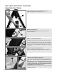
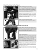
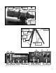
Fig. 1b: The Viewfinder close up.
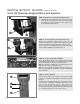
Fig. 1c: The Tripod.
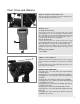
Fig. 1d: The Base Computer Control Panel.
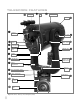
Fig. 1e: The Optical Tube Assembly (OTA) Computer Control Panel.