
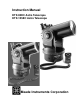
Manual


z
6
GETTING STARTED
CHAPTER
1
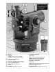
TELESCOPE FEATURES
Quick Tips
• Rotational Limits: The telescope base and fork mount are
designed with internal “rotational limit stops.” The horizontal
limit stop prevents the telescope from rotating more than
630° to avoid damage to the internal wiring. The vertical limit
stop prevents the viewfinder from contacting the fork mount
when the telescope is pointed upward just past 90° and
prevents the optical tube from contacting the base if pointed
downward more than 30°. Do not force the telescope to
move beyond these stops or damage to the telescope will
result.
• Vertical Lock;Declination Setting Circle: The vertical lock
knob (6, Fig. 1) is a knurled knob located on the fork arm to
the right of the focus knob (9, Fig. 1). Mounted beneath the
knob is a circular scale with no numbers. Do not confuse this
scale with the Dec setting circle (18, Fig. 1) on the opposite
fork arm which has a number scale used to locate
astronomical objects.
• A Note on Indoor V i ew i n g : While casual, low-power
observations may be made with the telescope through an
open or closed window, the best observing is always done
outdoors. Temperature differences between inside and
outside air and/or the low quality of most home window glass
can cause blurred images through the telescope. Do not
expect high-resolution imaging under these conditions.
Telescope Controls
An important array of features and manual controls facilitates
operation of an ETX telescope. Be sure to become acquainted
with all of these controls before attempting observa t i o n s
through the telescope.
Horizontal Lock (10, Fig. 1): Controls manual horizontal
rotation of the telescope while sitting upright as shown in Fig.1.
Turning the horizontal lock c o u n t e r c l o ck w i s e unlocks the
telescope, enabling it to be freely rotated by hand about the
horizontal axis. Turning the horizontal lock clockwise prevents
the telescope from being rotated manually, but engages the
horizontal motor drive clutch for Electronic Controller operation.
When polar aligned, the horizontal lock serves as the Right
Ascension, or R.A. lock (see Right Ascension, page 12).
Vertical Lock (6, Fig. 1): Controls manual vertical movement of
the telescope while sitting upright as shown in Fig. 1. Turning
the vertical lock c o u n t e r c l o ckwise unlocks the telescope
enabling it to be freely rotated by hand about the vertical axis.
Turning the vertical lock clockwise (to a firm feel only) prevents
the telescope from being moved manually, but engages the
vertical motor drive clutch for Electronic Controller operation.
When polar aligned, the vertical lock serves as the Declination,
or Dec lock (see Declination, page 12).
Focus Knob (9, Fig. 1): Causes a finely-controlled internal
motion of the telescope’s primary mirror to achieve precise
image focus. An ETX can be focused on objects from a
distance of about 11.5 ft (ETX-90EC) or 15 ft (ETX-125EC) to
infinity. Rotate the focus knob clockwise to focus on distant
objects; counterclockwise to focus on near objects.
Flip-Mirror Control (16, Fig. 1): Both ETX models include an
internal optically-flat mirror. With the flip-mirror control in the
“up” position, as shown in Fig. 1, light is diverted at a 90° angle
to the eyepiece. Alternately, with the flip-mirror control in the
“down” position, light proceeds straight through the telescope
and out the photo port (17, Fig. 1) for telephoto or astronomical
photography using the optional #64 T-Adapter, or for observing
with the optional #932 45° Erecting Prism (see
OPTIONAL
ACCESSORIES
, page 17).
NOTE: The flip-mirror control is in the “up” position when the
control is vertical (perpendicular to the telescope tube). It is
“ d ow n ” when the control is hori zontal (parallel with the
telescope tube).
Computer Control Panel
The computer control panel (Fig. 5) of the ETX-90EC and
ETX–125EC models include a connector for either the
standard-equipment Electronic Controller or the optional #497
Autostar Computer Controller, an external power supply
c o n n e c t o r, and two auxiliary ports (see
O P T I O N A L
ACCESSORIES
, page 16).
ON/OFF (1, Fig. 5): When the ON/OFF switch is moved to the
ON position, the red power indicator light (5, Fig. 5) illuminates
and power is supplied to the Electronic Controller and to the
telescope’s motor drive.
AU X (2, Fig. 5): Two identical auxiliary ports provide
connections for current and future Meade accessories.
CAUTION:Using products other than standard Meade
accessories may cause damage to the telescope’s
internal electronics and may void the Meade warranty.
HBX (3, Fig. 5): The HBX (handbox) port is designed to accept
the plug from the coil cord of the Electronic Controller or the
optional #497 Autostar Computer Controller.
12v (4, Fig. 5): The 12v connector is designed to accept an
external power supply such as the optional #541 AC adapter or
the #607 Power Cord (see
OPTIONAL ACCESSORIES
, page 18).
When one of these alternate powering options is used, the
internal batteries are disconnected from the power circuit.
NOTE: Always remove the batteries if they are not to be used
for a long period of time.
Electronic Controller Functions
The Electronic Controller provides the observer with the means
to control the telescope motors from a compact handbox. The
Electronic Controller (Fig. 6) has soft-touch keys designed to
have a positive feel, even through gloves.
Primary functions of the Electronic Controller are to move
(slew) the telescope, indicate the slew speed, and to operate
the optional #1244 (ETX-90EC) or #1247 (ETX-125EC) Electric
Focuser (see OPTIONAL ACCESSORIES, page 18). Other
functions are also possible when using the MODE key (see
Electronic Controller Modes, page 11 and APPENDIX A,
page 22).
Arrow Keys (1, Fig. 6): The four arrow keys slew the telescope
in four directions (i.e., up-and-down or left-and-right) at any one
of four slew speeds (see SPEED Key, page 7).
Important Note: While using the arrow keys to slew to an
object, when reversing direction there may be a slight
pause as the telescope motors compensate for the
reversal of the internal gears.
Fig. 5: Computer Control Panel. (1) ON/OFF switch; (2)
Auxiliary ports; (3) Handbox port; (4) 12v connector; (5)
Power indicator light.
5
1
2
2 3 4