Instruction Manual 20" MAX-ACF Advanced Coma-Free Telescope on MAX Robotic German Equatorial Mount MEADE.
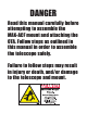
DANGER Read this manual carefully before attempting to assemble the MAX-ACF mount and attaching the OTA. Follow steps as outlined in this manual in order to assemble the telescope safely. Failure to follow steps may result in injury or death, and/or damage to the telescope and mount.
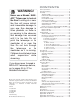
CONTENTS WARNING! ® Never use a Meade MAXACF™ Telescope to look at the Sun! Looking at or near the Sun will cause instant and irreversible damage to your eye. Eye damage is often painless, so there is no warning to the observer that damage has occurred until it is too late. Do not point the telescope or its viewfinder at or near the Sun. Do not look through the telescope or its viewfinder as it is moving. Children should always have adult supervision while observing.
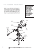
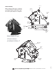
TELESCOPE FEATURES Note: Your telescope and mount may look slightly different from the one shown in some of the images in this manual. However, your telescope will still operate as the one described in this manual. Components of MAX MAX features a unique modular design that allows a couple of individuals to assemble, either permanently or transportably, a mount twice the size of any other commercially available mount.
RA Lock Knob Pedestal Assembly MAX's Pedestal assembly can be configured to cover three latitude ranges without the need of disassembly. Together, the three ranges allow the mount to operate anywhere on the planet.
Right Ascension Housing Assembly The RA Housing mates to the Pedestal easily, sliding firmly into a dovetail block that measures over 100 square inches. When locked in place, this broad footprint assures that your mount will operate as a single rigid block delivering accurate and repeatable pointing and tracking performance. The RA Housing contains Meade's patented Autostar II telescope control system, a massive 13.625" pitch diameter worm gear attached to a 3.
Declination Housing Assembly DEC ASSEMBLY The Dec Housing mates to the RA Housing using another huge dovetail block. The RA Housing, DEC Housing and Pedestal are all designed to allow you to track more than 6 degrees past meridian without interference. This mount will let you cover the whole sky.
pedestal attachment lever course adjustment lock lever fine adjustment turnbuckle THE TRIPOD MAX Tripod The MAX-ACF tripod can be transported or permanently installed. It provides a wide stance to assure that it can safely carry MAX's massive payload in all orientations, but still collapses down to a size that is easy to handle. Its design assures that despite its wide stance, it will not interfere with optical systems observing on the meridian.
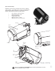
Optical Tube Assembly MAX-ACF is delivered with a 20” Advanced Coma-Free™ Optical Tube Assemblie. Its 20” OTA integrates seamlessly with MAX-ACF German Equatorial Mount.
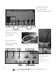
CONTROL PANELS AND PORTS Off/On 12vDC In USB Port 12VDC Switched Out AUX port HBX port (Handbox port) Serial port RA ASSEMBLY CONTROL PANEL SADDLE CONTROL PANEL Reticle Port 12VDC Switched RA TO DEC JUMPER CABLE Focuser Smart Accessory Ports JUMPER CABLE BETWEEN OTA AND SADDLE PANEL (may use either of the Smart Accessory ports) USB Ports 10 Auto Guider HBX port Looking at or near the Sun will cause irreversible damage to your eye. Do not point this telescope at or near the Sun.
AUTOSTAR II FEATURES 쐈 쐅 Fig. 2: The Autostar II Handbox. Tour the Cosmos with Just the Push of a Button Control of MAX-ACF telescope is through the operation of the standard Autostar II system. Nearly all functions of the telescope are accomplished with just a few pushes of Autostar II’s buttons. Because the Autostar II system uses flash (rewritable) memory, your system will be able to grow when new features and enhancements become available.
The Autostar II system provides control of virtually every telescope function. The Autostar II handbox has soft-touch keys designed to have a positive feel. The LCD (Liquid Crystal Display) is backlit with red LEDs (Light Emitting Diodes) for easy viewing in the dark. The backlit display, key arrangement, and sequential menu structure make Autostar II extremely user friendly. B c d e f 2-Line LCD Display: This screen displays Autostar II's menus and information about the telescope.
4 FOCUS: Toggles between two functions. The first press allows you to change the focus and focus speed. The next press allows you to create presets that tell the telescope where to focus. 5 SS: Press to display the Solar System library. 6 STAR: Press to display the Star library. 7 RET (Reticle): Press to display the Reticle Control menu. 8 IC: Press to display the Index Catalog library. 9 NGC (New General Catalog): Press to display the NGC catalog library.
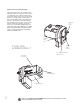
ASSEMBLY Refer to images pages 4 to 10 for location of various telescope features. A screwdriver or other 1/4" shaft that can be used as a lever will be useful during assembly. Pointing to ± 5° of the pole 1 2 Tripod Assembly Before you pull legs out of collapsed tripod, notice the pattern of the pins on top of the tripod (photo). Set the legs so the leg opposite the single pin is pointing North.
5 Tighten (rotate) the lock knobs below the Pedestal to a "tight" feel. First loosely tighten all three knobs, then tighten all three securely. 6 Back off the ejector knobs on the Pedestal. 7 Adjust legs until they are level. Adjust the turnbuckle for fine adjustment of level. The bubble levels will assist you. in determining level.
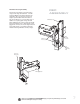
9 B Fine tune the latitude adjustment using the Latitude Adjust knob. See APPENDIX D if you need help reading the latitude scale. Latitude Adjust Knob Is your telescope pointing North? Is your telescope level? Make sure you are pointing North and are level before proceeding. THE RA ASSEMBLY Turn the Dec Lock knobs on the RA assembly until there is NO a gap in the clamps. 10 no gap Slide the RA assembly onto the Pedestal dovetail.
THE DEC SADDLE ASSEMBLY Turn the Dec lock knob so there is no gap (see step 10). Note, in the photos, the Dec assembly is already shown as attached. However, adjust this knob before 13 you attach the assembly. CAUTION: MAKE SURE THAT YOUR FINGERS ARE CLEAR OF THE TRACK BEFORE YOU SLIDE THE RA ASSEMBLY INTO THE PEDESTAL TRACK. THE RA ASSEMBLY REQUIRES TWO PEOPLE TO LIFT. 14 A 14 B With a person on each side of the assembly, lift and slide the DEC assembly in from the top... ...
17 Retighten the Dec clamp knob. 18 Plug in the RA to Dec jumper cables; there are two (2) such cables. The first being a 25 pin to 25 pin cable and the second a USB to USB cable. Hint: You may wish to plug into the RA connector before attaching the counterweights. Then attach the jumper cable to the Dec assembly after the weights are attached. Some users may find it difficult to reach in below the Dec assembly to connect the cable after the counterweights are attached.
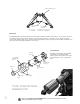
close up of Indentation on fixed counterweights 21 A 21 B 22 Slide the bolts into the threaded holes and tighten each securing knob by hand until it reaches the top. Then use a 1/4" shaft, such as a Phillips screwdriver, as a lever, to turn the knob very tight. Screw in counterweight shaft into the bottom of the fixed counterweight assembly until it reaches the hard stop. Slide a screwdriver or shaft into into the hole on the 23 head of the shaft (see photo).
Put on adjustable counterweights (three for 20 inch models, two for 16 inch models). The weights can be more easily if you make this a two person job. 24 attached One person holds weight and holds in button. Other perB son pushes the weight up the shaft; slide up to within one inch of the end of travel. Push counterweights up against one another. 25 Screw the safety cap on the end of the shaft after the counterweights are attached.
The OTA should have its dust cover attached when left stored on the ground in an upright position. You can also store it on its side. 28 A A minimum of four people are needed to lift the optical tube. DANGER!: MAKE SURE THAT THE COUNTERWEIGHTS 28 ARE ATTACHED BEFORE PROCEEDING WITH THIS B STEP. SEE STEPS 17 THROUGH 22. IMPORTANT! DANGER!: DUE TO THE WEIGHT AND SIZE OF THE 20" OPTICAL TUBE, PLEASE USE EXTREME CAUTION WHENEVER ASSEMBLING, DISASSEMBLING, LIFTING, TRANSPORTING OR STORING THIS PRODUCT.
29 A ELECTRICAL CONNECTIONS Connect the Smart Accessory port on the Saddle control panel to OTA using the 9-pin jumper cable. You may use either of the Smart Acc ports on the control panel. the OTA cable to the saddle plate. Plug in 29 Attach "12VDC IN;" make sure power switch is turned off first. B Plug in handbox to HBX and plug in any other accessories. Slide in the included 2" accessory adapter, a diagonal 30 eyepiece holder and an eyepiece. Tighten thumbscrews to secure.
HOME POSITION AND BALANCING THE OTA After power is applied and Autostar has initialized, press MODE to move to the vertical home position (see photo at left). 33 A C A U T I O N: BEFORE D I S A S S E M B L I N G, THE TELE- SCOPE MUST BE PUT INTO THE HOME POSITION. Before using the telescope, you will need to balance it in both the RA and Dec axes. Before you balance, attach the eyepiece assembly, the viewfinder and all the accessories you will be using with the telescope (cameras, 33 guide scopes, etc.).
Perpendicular to home position When the display readout is close to "1" (perhaps .99 1.01) and remains close to 1 while it is moving, it is 36 or balanced. Press MODE. This stops the Balance procedure. Next move the telescope so that it is 90° perpendicular to the Home Position. Select Balance RA once again and press ENTER. Repeat the same procedure in the perpendicular position. Once again, move the weights to get the balance readouts to get close to 1.
GETTING STARTED c b To Attach the handbox holder: Remove the handbox holder from the plastic bag. If necessary, loosen the lock knob (1, Fig. 39a) and place the clamp (2, Fig. 39a) about one of the telescope's handles. Tighten the lock knob to a firm feel. Slide the AutoStar II handbox into the holder (3, Fig. 39a).You may also snap the handbox into the holder: Slide one side of the handbox into the holder and then firmly press the other side of the handbox into the holder until it snaps in place.
Focusing the Telescope All focusing is performed digitally, using AutoStar II’s Focus key (number key 4). The Focus key functions as a toggle key: 1@ 쩦 Press the Focus key the first time to focus the telescope eyepiece and to control the speed at which you focus. 1# Fig. 40d: Viewfinder adjustment screws (12); spring loaded screw (13) Fig. 40e: Align the viewfinder on a distant object, such as a light or telephone pole. Important Note: Press MODE at any time to exit Focus modes.
scope), you can use Autostar to control both the MAX-ACF and the microfocuser. Make sure you have connected the saddle plate to the MAX-ACF and the microfocuser to your telescope and also the saddle plate's Focuser port. Follow this procedure: • Important Note: Press MODE at any time to exit Focus modes. Press the Number Key 4 and Autostar displays "OTA: Fast" displays. You are now in control of the MAX-ACF focuser. • Use the Up/Down keys to scroll through the MAX-ACF focuser speeds.
Aligning for the First Time Important Note: First time you align the telescope, perform the following procedures to insure precision pointing: 1. Automatic Align 2. Drift Align 3. Collimation 4. OTA Align (if non -MAX-ACF model) 5. Calibrate home. If you wish to have precise pointing accuracy, the first time you align your telescope you will need to align it to using Automatic Alignment and Drift Alignment. You will then electronically collimate the telescope, square the OTA and finally calibrate home.
How to Drift Align Max (Northern Hemisphere) Important Note: You will need a reticle to perform this procedure Note: See: http://www.astrocruise.com /polarnew.htm for a website dedicated to drift alignment of Meade telescopes. Site offers extensive tips from an experienced drift align specialist. 1. Center your reticle on a bright star near the Eastern horizon. 2. Look through the reticle while pressing Autostar's right and left Arrow keys. This will slew the mount back and forth in the R.A. axis. 3.
Follow these steps for collimation of the optical system: The only adjustments possible, or necessary, on the MAX-ACF models is performed with the AutoStar handbox. No adjustment screws are necessary (or provided), as with traditional telescopes. A high-powered eyepiece, such as a 9mm eyepiece, or a 9mm eyepiece with a 2x barlow, is required for collimation.
alignment routine. When centered, tighten just the center bolt. This will hold the bolts securely in that position. Note that there is a bolts on either side of the OTA align bolt (Fig. 42b). These bolts must be loosened during the procedure and tightened afterward. Calibrate Home: After aligning your telescope, select this menu and the alignment settings—North, time, alignment stars—are stored in Autostar II's memory and are remembered after you power off the telescope.
BASIC AUTOSTAR II SETUP MENU Automatic alignment permits all telescope operations with only minimal setup. Select Item: Object Select Item: Setup UTILITIES MENU Calculate eyepiece magnifications; set timer alerts; create your own landmark survey.
4. Press the Scroll Down key once to display the "Sunset" option in the Event menu. 5. Press the ENTER key to choose the "Sunset" option and move down another level. 6. Autostar II calculates the Sunset time based on the current date, time, and location. Autostar II then displays the results of the calculation. 7. Press MODE once to start moving back up through the Autostar II levels. The first level up is the Event menu. 8. Press MODE again to move up another level.
Looking at or near the Sun will cause irreversible damage to your eye. Do not point this telescope at or near the Sun. Do not look through the telescope as it is moving. Moon Overview Landing Sites Apollo 11 etc. Craters Abbot etc. Mountains Mons Bradley etc. Mare, Lakes Lacus Aestatis etc. Valley, Rills Rima Agatharchid etc. Select Item Guided Tour Tour Objects Tonight's Best How Far is far etc.
Object Menu Almost all observing with Autostar II is performed using the Object menu category. (Note: Exceptions include Guided Tour and Landmark Survey.) Autostar II contains many libraries of viewable objects, such as stars, planets, comets, nebulae and so forth. When one of these objects is selected from a library, Autostar II moves your telescope (if properly aligned) and points it at the selected object. Six of the most popular libraries can be accessed directly using the hot buttons.
Browse: Allows you to search the library for objects with certain parameters, much like a search engine. "Edit Parameters" lets you set various parameters for the search, such as: Object Type, Minimum Elevation, Largest, etc. Once you have set the parameters of the search, select "Start Search" and press ENTER. Autostar II will display the results of the search. Event Menu The Event menu provides access to dates and times of astronomical events.
OTA Fan: Allows you to turn the fan off or on if you have an MAX-ACF model. The fan assists with the stabilization of the optics. The fan should be activated at the beginning of an observing session and run until the optics have achieved an equilibrium with the environment. Fan operation time should range from about 5 to 25 minutes. Note that the fan may introduce a slight vibration and this may cause noticeable movement observed with sensitive optics.
prompts you to turn off the telescope's power, Autostar II is unable to be returned to operation without turning the power off and then back on. Setup Menu There are numerous other features available within the Setup menu, including: Align: Let's you choose a method of alignment. Align on Home: If Calibrate Home has been performed, power up your telescope and select this menu to return the previously calibrated home position.
in the sky. a. b. c. c. Sidereal: The default setting for Autostar II; sidereal rate is the standard rate at which stars move from East to West across the sky due to the rotation of the Earth. Lunar: Choose this option to properly track the Moon over long observing sessions. Solar: Choose this option when observing the Sun. Custom: Allows entry of user-defined tracking rates. Note: Custom Tracking Rate allows you to enter values from -999.999 to 999.999.
GPS-UTC Offset: Universal Time (UTC) allows you to add leap seconds to its time calculations, GPS does not. The offset is the number of leap seconds added since the establishment of GPS. Site: Site provides access to several options including: 쩦 Select: Displays the currently selected observing site. Use the Scroll keys to cycle through all available sites (see ADD below). Press ENTER when the site you wish to select displays. Use this option when you move to a different geographic location.
쩦 Serial Number: Displays the unit's serial number. Reset: Completely resets Autostar II. Most values entered into the menus revert to factory defaults. Autostar II requires initialization again after a Reset before proceeding with observations. "Hot Button" Menus Two menus, six object libraries and two functions can be accessed directly using the Number keys (commonly referred to as "hot buttons"). The two functions, the Speed mode and the Utility light are described earlier in the manual.
ADVANCED AUTOSTAR II FEATURES Before trying out the examples in this section, familiarize yourself with the basic operations of Autostar II described earlier in this manual. The following examples assume that you have a basic knowledge of Autostar II and understand how to scroll to a desired menu or menu option, and how to enter numbers and text. It also assumes that you have initialized and aligned your telescope.
11. Press MODE. "Site: Edit" displays. 12. Using the Arrow keys, scroll to "Site: Select." The site you have just edited displays. Press ENTER to select the site. Creating User Objects In this procedure, you will enter coordinates of celestial objects that do not appear in any of the Autostar II libraries.You will enter the object's name and R.A. and Dec. coordinates (required information). You may also enter the object's magnitude and size (optional information).
Observing Satellites In this procedure, you will prepare your telescope to observe a satellite pass. 1. Navigate to the "Object: Satellite" menu option and press ENTER. 2. Use the Scroll keys to scroll through the list of satellites. 3. Select a satellite from the list and press ENTER. 4. "Calculating...." and then "Tracking..." displays. If the satellite is going to make a pass, "Located" displays. 5. Use the Scroll keys to display data about the pass: aos—acquisition of signal and los—loss of signal.
2. Navigate to the "Object: Identify" option and press ENTER. 3. "Searching..." displays. When Autostar II finishes calculating, the name of the closest object displays. 4. Press a Scroll key to display information about this object.
Alternate Polar Alignments If you would rather set up your telescope without using automatic alignment, Autostar II offers alternative alignment methods for equatorial mounting. During the One-Star and Two-Star alt/az alignment procedures, you will (unlike the Automatic and Easy alignment procedures) manually place the telescope in the home position.
computer control panel/ Plug the other end into a USB port of your PC Next, you will install the Autostar Suite software from the CD ROM. This software provides a menu that allows you to download the latest version of Autostar II software into the Autostar II handbox. 4. Select Autostar Suite on the CD ROM to install Autostar Suite onto your PC. Follow the on-screen instructions. 5. Once the Autostar Suite software installs, double-click the new “Autostar Suite” icon on the desktop. 6.
OPTIONAL ACCESSORIES A wide assortment of professional Meade accessories is available for the MAX-ACF telescope models. The premium quality of these accessories is well-suited to the quality of the instrument itself. Consult the Meade General Catalog for complete details on these and other accessories. Meade Series 4000 Eyepieces: 16” f/8 Power/Actual Field Eyepiece 20” f/8 Power/Actual Field Plössl Eyepieces (5 elements; 1.25” O.D., except as noted) Fig. 46: Series 5000 5 Element Plossl Eyepieces. 5.
Series 4000 Nebular Filters: A modern boon to the city-dwelling deep-space observer, the interference nebular filter effectively cancels out the effects of most urban light pollution, while leaving the light of deep-space nebular emissions virtually unattenuated. Meade Series 4000 Nebular Filters utilize the very latest in coating technology, and are available with threaded cells for eyepieces or for attachment to the rear cells of Meade Schmidt-Cassegrain models. Fig.
#1A filter. The filter increases visual and photographic contrast, decreases glare, and helps to penetrate haze. MAX-ACF AC Wall Adapter: Permits powering from a standard home (115v AC) outlet. Cigarette Lighter Adapter: Powering the MAX-ACF telescope by means of an automobile cigarette lighter plug. #644 Flip Mirror System: Has an X/Y adjustment mechanism for the diagonal mirror with locks for the precise centering, and multiple rotating adapters for T-thread and 1.25” camera attachment. Accepts 1.25” O.D.
MAINTENANCE MAX-ACF telescopes are precision optical instruments designed to yield a lifetime of rewarding applications. Given the care and respect due any precision instrument, your MAX-ACF will rarely, if ever, require factory servicing. Maintenance guidelines include: a. Avoid cleaning the telescope’s optics: A little dust on the front surface of the telescope’s correcting lens causes virtually no degradation of image quality and should not be considered reason to clean the lens. b.
TELESCOPE SPECIFICATIONS Total instrument capacity . . . . . . . . . . . . . . . . . . . . . . . . . . . . . Aperture . . . . . . . . . . . . . . . . . . . . . . . . . . . . . . . . . . . . . . . . . . Optical design . . . . . . . . . . . . . . . . . . . . . . . . . . . . . . . . . . . . . Optical coatings . . . . . . . . . . . . . . . . . . . . . . . . . . . . . . . . . . . . Mount . . . . . . . . . . . . . . . . . . . . . . . . . . . . . . . . . . . . . . . . . . . . Gear pitch diameter . . . . . . . . .
Weights and Dimension RA Housing Assembly Dec Housing Assembly Counterweight Shaft Assembly Individual Counterweight Portable Tripod Footprint radius: 30 inches Permanent Pier Optical Tube Assembly (OTA) 20” MAX-ACF OTA 20" OTA + MAX-ACF + Counterweights Optional Accessories Weights 66 pounds 75 pounds Dimensions L = 20.75"; W = 18.85"; H = 20.34". L = 18.25"; W = 15"; H = 20.45". 35 pounds 81 pounds L = 5.9"; W = 5.9"; H = 2.96". Height: 26.
APPENDIX A: LATITUDE CHART Latitude Chart for Major Cities of the World To aid in the polar alignment procedure, latitudes of major cities around the world are listed below. To determine the latitude of an observing site not listed on the chart, locate the city closest to your site. Then follow the procedure below: Northern hemisphere observers (N): If the site is over 70 miles (110 km) North of the listed city, add one degree for every 70 miles.
APPENDIX B: THE MOON The Moon option of the Object menu allows you to observe the moon in a way never possible before. You will be able locate many specific features of the lunar surface, including hundreds of craters, mare, valleys, and mountains. One special feature allows you to view all six Apollo landing sites.
APPENDIX C: Smart Mount Introduction Smart Mount improves the pointing accuracy of your MAX-ACF telescope's "Go to" system. Despite careful efforts to calibrate and align telescopes, they may fail to precisely center objects. Smart Mount allows your telescope to learn about, and then correct for, any systematic pointing errors, regardless of the cause.
• Save your model, using a good, descriptive name, using the “Save As” menu. Upon completion of the training, Smart Mount is enabled and remains on until you choose “Off” from the Smart Mount Configuration menu. Permanently Mounted Scopes For permanently mounted telescopes, it is not necessary to have more than one model unless the weight and balance of auxiliary equipment introduces balance or flexure changes that significantly affect pointing.
APPENDIX D: How to Read the Latitude Scale Introduction As Max needs to be polar aligned, you will need to set the latitude scale for you latitude range. The Latitude scale has three sets of measurements, one for each latitude range: 0 to 30°, 30° to 60° and 60 to 90°. Note that there are five extra degrees beyond both 0 and 90°. This allows you to add for latitudes just slightly below 0 and just slightly above 90 degrees.
MEADE LIMITED WARRANTY Every Meade telescope, spotting scope, and telescope accessory is warranted by Meade Instruments Corporation (“Meade”) to be free of defects in materials and workmanship for a period of ONE YEAR from the date of original purchase in the U.S.A. and Canada. Meade will repair or replace a product, or part thereof, found by Meade to be defective, provided the defective part is returned to Meade, freight-prepaid, with proof of purchase.