
User`s guide


MDS 05-2806A01, Rev. E.1 MDS iNET 900 Series User’s Guide 149
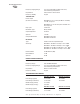
NOTE: Range calculations for fixed locations assume a 6 dBd gain
Omnidirectional antenna on a 100 ft tower at the AP, a 10 dBd
gain Yagi on a 25 ft mast at the remote with output power
decreased to yield maximum allowable EIRP (36 dBm), a 10
dB fade margin, and a mix of agricultural and commercial
terrain with line of sight.
Range calculations for mobile units assume a 6 dBd gain Omni
on a 100 ft tower at the AP, a 5 dBd gain Omni with 1 watt
output power at 6 ft height, a 10 dB fade margin, and 90%
confidence with near line-of-sight in a mix of agricultural and
commercial terrain.
Actual performance is dependent on many factors including
antenna height, blocked paths, and terrain.
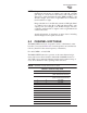
6.4 CHANNEL HOP TABLE
The MDS iNET transceiver’s hop table consists of 80 channels, num-
bered 0 to 79 as listed in Table 6-4. Center frequencies are calculated as
follows (where Fn is the center frequency of channel n):
Fn = 902.5 MHz + n*316.5 kHz
The MDS iNET II transceiver operates on the same channel assign-
ments, but because the modulation bandwidth is 600 kHz instead of
316.5 kHz it is recommended that the installer restrict channel usage to
every other channel for units operating in the same area.
NOTE: Channels 24, 26, and 55 are not used.
Table 6-4. Channel Hop Table
Zone Channel Frequency
1 0 902.5000
(iNET FHSS lowest channel)
1 1 902.8165
(iNET II DTS lowest channel)
1 2 903.1330
1 3 903.4495
1 4 903.7660
1 5 904.0825
1 6 904.3990
1 7 904.7155
2 8 905.0320
2 9 905.3485
2 10 905.6650
2 11 905.9815
2 12 906.2980