
Instruction manual


Table Of Contents
- Introduction
- Using the Keypad/Display
- Keypad/Display Menu Structure
- System Summary Menu
- Standard Menus
- System Menu
- Occupancy Menu
- Temperature Menu
- Flow Summary Menu
- Supply Fan Speed Menu
- Return/Exhaust Fan Speed Menu
- Cooling Menu
- Head Pressure Menu
- Evap Condensing Menu
- Economizer Menu
- Min OA Damper Menu
- Heating Menu
- Energy Recovery
- Dehumidification Menu
- Daily Schedule Menu
- One Event Schedule Menu
- Holiday Schedule Menu
- Optimal Start Menu
- Operating Hours Menu
- Extended Menus
- Unit Setup Menu
- Timer Settings Menu
- Time/Date Menu
- Supply Fan Setup Menu
- Return/Exhaust Fan Setup Menu
- Zone Temperature Setup Menu
- Compressor Setup Menu
- Head Pressure Setup Menu
- Chilled Water Setup Menu
- Economizer Setup Menu
- Design Flow Setup Menu
- Heating Setup Menu
- Dehumidification Setup Menu
- Alarm Out Configuration Setup Menu
- Alarm Limits Setup Menu
- Manual Control Menu
- LON/BACnetIP/BACnetMSTP Setup Menu
- Active Alarm Menu
- Alarm Log Menu
- Advanced Menus
- Unit Configuration Setup Menu
- Save/Restore Menu
- Alarm Delays Setup Menu
- Analog Input Status Menu
- Universal I/O Status Menu
- Digital Input Status Menu
- Digital Output Status Menu
- Adv Setup Settings Menu
- Adv Status Parameters Menu
- Alarms
- Operator’s Guide
- Determining Unit State
- Off Operating State
- Start Up Operating State
- Recirculating Operating State
- Heating
- Economizer
- Mechanical Cooling
- Determining Unit Status
- Determining Control Mode
- Determining Cooling Status
- Determining Heat Status
- Determining Economizer Status
- Determining Cooling Capacity
- Determining Heating Capacity
- Determining Supply Air Fan Capacity
- Determining RF/EF Capacity
- Determining Outside Air Damper Position
- Determining Emergency Mode
- Determining Application Mode
- Determining Occupancy Status
- Determining Occupancy Mode
- Determining Occupancy Source
- Unoccupied Operation
- Scheduling
- Temperature Control Configurations
- Heat/Cool Changeover
- Dehumidification
- Energy Recovery
- Outside Air Damper Control
- Outside Air Damper Control, Two Position
- Special Procedures for Units with WRV and More Than Two Circuits.
- Water Pump Control
- Cooling: Multistage
- Cooling: Modulating
- Heating Control
- Modulating
- Min DAT
- Indoor Air Fan - On/Off Control
McQuay OM 920 99
Operator’s Guide
Eight Equal Sized Compressors, Eight Circuits, WRV
Only one sequence is provided so the user makes no selections.
• Total cooling stages = 8.
• Maximum cooling stages is always set to 8.
• If both circuit # 1 and circuit # 2 are enabled, the staging sequence is Std-1 if compressor # 1
has fewer hours than compressor # 2, and the staging sequence is Std-2 if compressor # 1
does not have fewer hours than compressor # 2.
• If Circuit # 1 is disabled, the staging sequence is Std-2.
• If Circuit # 2 is disabled, the staging sequence is Std-1.
• If both circuit # 1 and circuit # 2 are disabled, the staging sequence is Std-1. Only
compressors 3 through 8 are used.
• The Compressor Sequence changes based on Run Time only when the compressor stage
equals Maximum cooling stages or zero. This means that disabling and re-enabling the
compressors or turning the unit off and on may be necessary to cause sequence changes.
• The compressor sequence changes immediately if a circuit is disabled to keep either
compressor # 1 or # 2 on. This will result is compressors being turned off and others being
turned on in this emergency condition.
• The same staging sequence is used whether a circuit is disabled or not. This means that units
will remain at a stage for an extra stage time when staging up if a disabled circuit is added at
that stage. It also means that units will remain at a stage for an extra stage times when
staging down if a disabled circuit is turned off at that stage.
• Any compressor on a disabled circuit stays off if it is already off and is turned off if it is on.
Staging - DAT Control
In the Cooling state, compressor stages are turned on and off to maintain an average Discharge
Air Temperature near the Discharge Cooling Setpoint. This control sequence causes the unit to
operate longer at the stage that produces the discharge air temperature that is closer to the
setpoint which results in an average discharge air temperature that is very close to the
Discharge Cooling Setpoint. This setpoint may be fixed or reset as described in the Cooling
DAT Reset section. External devices such as VAV boxes maintain the desired space
conditions. The unit may be a Constant Volume unit, but it is normally a Variable Air Volume
unit. If the Discharge Air Temperature is approaching the setpoint, the number of stages
continues to increase or decrease until the actual temperature gets within half the deadband.
Control of cooling stages is based on two values, the Degree Time Above and the Degree
Time Below the cooling DAT setpoint. The difference between the actual discharge air
temperature and the Discharge Cooling Setpoint is added to one of the Degree Time values
every ten seconds. If the Discharge Air Temperature exceeds Discharge Cooling Setpoint, the
difference is added to the Degree Time Above Value. If the Discharge Air Temperature is
below the Discharge Cooling Setpoint, the difference is added to the Degree Time Below
value. These values are limited to a maximum value of 250 to prevent getting stuck in one
stage because one value or the other became very large.
When the unit enters the Cooling state the unit goes directly to Cooling Stage # 1 so that the
first compressor is turned on immediately unless the unit is configured for Evaporative
Condensing. In this case, the sump pump must be turned on before any compressor is turned
on. If there is a sump pump fail condition, cooling will stay in stage 0.
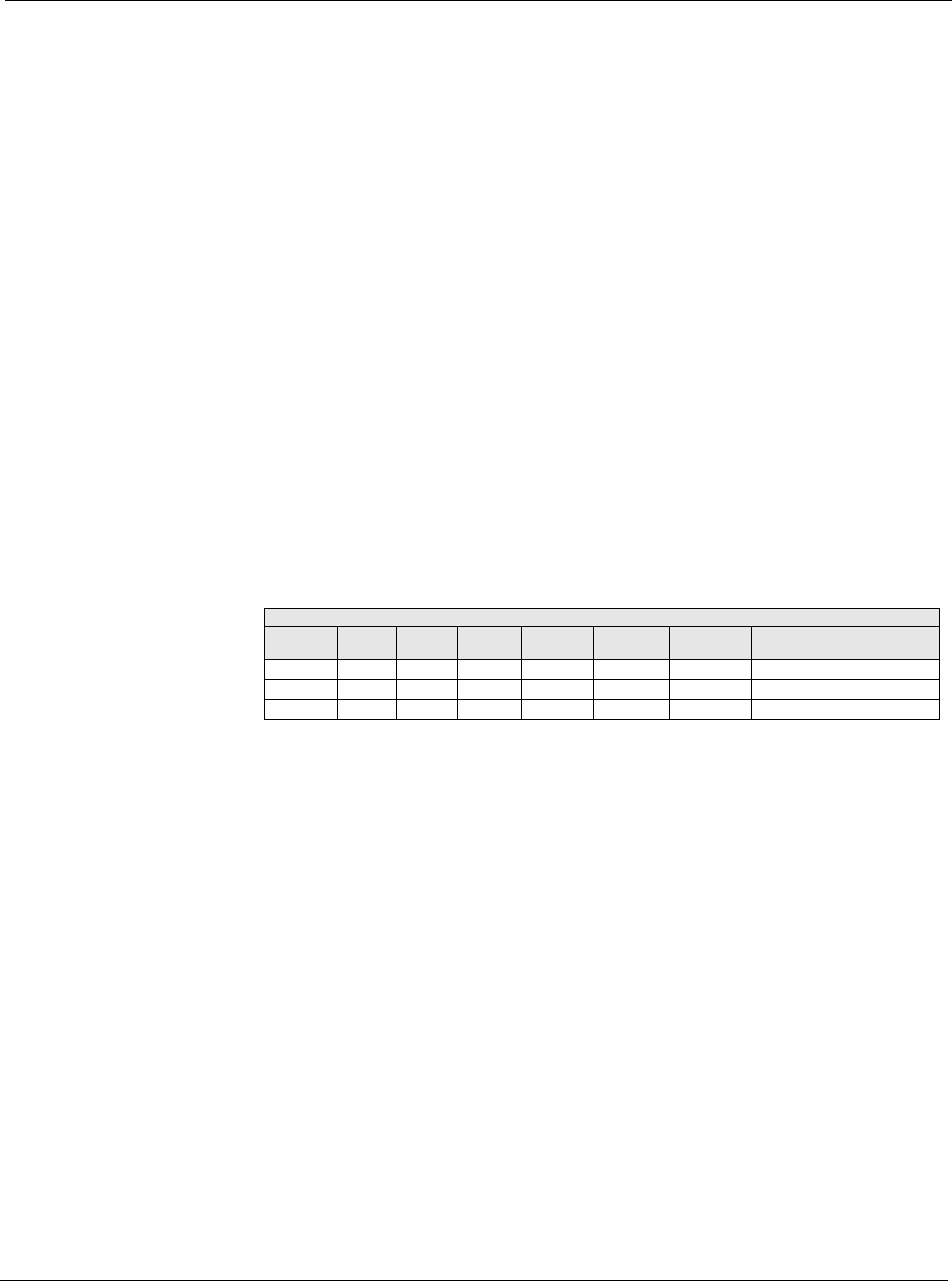
Table 70: Standard Staging
Standard Staging
Staging
Sequence
Stage 1
Comps
Stage 2
Comps
Stage 3
Comps
Stage 4
Comps
Stage 5
Comps
Stage 6
Comps
Stage 7
Comps
Stage 8 Comps
Std-1 1 1,4 1,4,5 1,4,5,7 1,4,5,7,8 1,4,5,6,7,8 1,2,3,4,5,6,8 1,2,3,4,5,6,7,8
Std-2 2 2,3 2,3,6 2,3,6,8 2,3,6,7,8 2,3,5,6,7,8 2,3,4,5,6,7,8 1,2,3,4,5,6,7,8
ClgCap 13% 25% 38% 50% 63% 75% 88% 100%