
Instruction manual


Table Of Contents
- Introduction
- Using the Keypad/Display
- Keypad/Display Menu Structure
- System Summary Menu
- Standard Menus
- System Menu
- Occupancy Menu
- Temperature Menu
- Flow Summary Menu
- Supply Fan Speed Menu
- Return/Exhaust Fan Speed Menu
- Cooling Menu
- Head Pressure Menu
- Evap Condensing Menu
- Economizer Menu
- Min OA Damper Menu
- Heating Menu
- Energy Recovery
- Dehumidification Menu
- Daily Schedule Menu
- One Event Schedule Menu
- Holiday Schedule Menu
- Optimal Start Menu
- Operating Hours Menu
- Extended Menus
- Unit Setup Menu
- Timer Settings Menu
- Time/Date Menu
- Supply Fan Setup Menu
- Return/Exhaust Fan Setup Menu
- Zone Temperature Setup Menu
- Compressor Setup Menu
- Head Pressure Setup Menu
- Chilled Water Setup Menu
- Economizer Setup Menu
- Design Flow Setup Menu
- Heating Setup Menu
- Dehumidification Setup Menu
- Alarm Out Configuration Setup Menu
- Alarm Limits Setup Menu
- Manual Control Menu
- LON/BACnetIP/BACnetMSTP Setup Menu
- Active Alarm Menu
- Alarm Log Menu
- Advanced Menus
- Unit Configuration Setup Menu
- Save/Restore Menu
- Alarm Delays Setup Menu
- Analog Input Status Menu
- Universal I/O Status Menu
- Digital Input Status Menu
- Digital Output Status Menu
- Adv Setup Settings Menu
- Adv Status Parameters Menu
- Alarms
- Operator’s Guide
- Determining Unit State
- Off Operating State
- Start Up Operating State
- Recirculating Operating State
- Heating
- Economizer
- Mechanical Cooling
- Determining Unit Status
- Determining Control Mode
- Determining Cooling Status
- Determining Heat Status
- Determining Economizer Status
- Determining Cooling Capacity
- Determining Heating Capacity
- Determining Supply Air Fan Capacity
- Determining RF/EF Capacity
- Determining Outside Air Damper Position
- Determining Emergency Mode
- Determining Application Mode
- Determining Occupancy Status
- Determining Occupancy Mode
- Determining Occupancy Source
- Unoccupied Operation
- Scheduling
- Temperature Control Configurations
- Heat/Cool Changeover
- Dehumidification
- Energy Recovery
- Outside Air Damper Control
- Outside Air Damper Control, Two Position
- Special Procedures for Units with WRV and More Than Two Circuits.
- Water Pump Control
- Cooling: Multistage
- Cooling: Modulating
- Heating Control
- Modulating
- Min DAT
- Indoor Air Fan - On/Off Control
94 McQuay OM 920
Operator’s Guide
Four Equal Sized Compressors, Four Circuits, No WRV
Only one sequence is provided so the user makes no selections
• Total cooling stage = 4.
• Maximum cooling stages is always set to 4.
• The Staging sequence is the Standard sequence that contains the enabled Stage 1
Compressor with the fewest run hours. Compressors in disabled circuits are ignored when
only enabled compressor run hours are compared. Maximum cooling stages is set to 4.
• The Compressor Sequence changes only when the compressor stage equals Maximum
cooling stages or zero. This means that disabling and re-enabling the compressors or turning
the unit off and on may be necessary to cause sequence changes.
• The same staging sequence is used whether a circuit is disabled or not. This means that units
will remain at a stage for an extra stage time when staging up if a disabled circuit is added at
that stage. It also means that units will remain at a stage for an extra stage times when
staging down if a disabled circuit is turned off at that stage.
• Any compressor on the disabled circuit stays off if it is already off and is turned off if it is
on.
Four Equal Sized Compressors, Four Circuits, Water Regulating Valve
Only one sequence is provided so the user makes no selections
• Total cooling stages = 4.
• Maximum cooling stages is always set to 4.
• If neither circuit # 1 nor circuit # 2 is disabled, the staging sequence is Std-1 if compressor #
1 has fewer hours than compressor # 2, and the staging sequence is Std-2 if compressor # 1
does not have fewer hours than compressor # 2.
• If Circuit # 1 is disabled, the staging sequence is Std-2.
• If Circuit # 2 is disabled, the staging sequence is Std-1.
• If both circuit # 1 and circuit # 2 are disabled, the staging sequence is Std-1. Only
compressors 3 and 4 are used.
• The Compressor Sequence changes based on Run Time only when the compressor stage
equals Maximum cooling stages or zero. This means that disabling and re-enabling the
compressors or turning the unit off and on may be necessary to cause sequence changes.
• The compressor sequence changes immediately if a circuit is disabled to keep either
compressor # 1 or # 2 on. This will result in compressors being turned off and others being
turned on in this emergency condition.
• The same staging sequence is used whether a circuit is disabled or not. This means that units
will remain at a stage for an extra stage time when staging up if a disabled circuit is added at
that stage. It also means that units will remain at a stage for an extra stage time when staging
down if a disabled circuit is turned off at that stage.
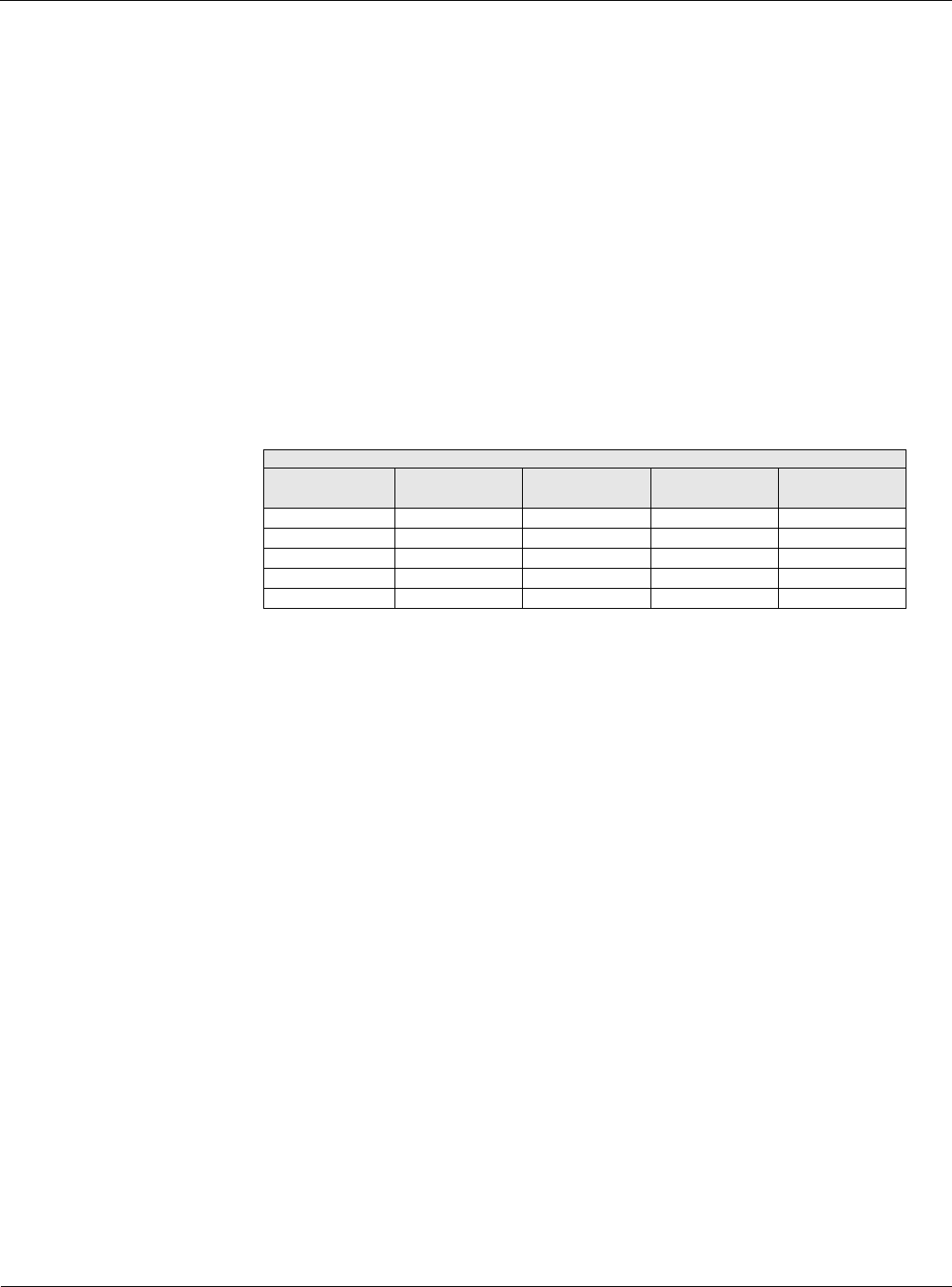
Table 61: Standard Staging
Standard Staging
Staging Sequence Stage 1
Compressor
Stage 2
Compressors
Stage 3
Compressors
Stage 4
Compressors
Std-1 1 1,2 1,2,3 1,2,3,4
Std-2 2 2,3 2,3,4 1,2,3,4
Std-3 3 3,4 1,3,4 1,2,3,4
Std-4 4 1,4 1,2,4 1,2,3,4
StgdClgCap 25% 50% 75% 100%