
Instruction manual


Table Of Contents
- Introduction
- Using the Keypad/Display
- Keypad/Display Menu Structure
- System Summary Menu
- Standard Menus
- System Menu
- Occupancy Menu
- Temperature Menu
- Flow Summary Menu
- Supply Fan Speed Menu
- Return/Exhaust Fan Speed Menu
- Cooling Menu
- Head Pressure Menu
- Evap Condensing Menu
- Economizer Menu
- Min OA Damper Menu
- Heating Menu
- Energy Recovery
- Dehumidification Menu
- Daily Schedule Menu
- One Event Schedule Menu
- Holiday Schedule Menu
- Optimal Start Menu
- Operating Hours Menu
- Extended Menus
- Unit Setup Menu
- Timer Settings Menu
- Time/Date Menu
- Supply Fan Setup Menu
- Return/Exhaust Fan Setup Menu
- Zone Temperature Setup Menu
- Compressor Setup Menu
- Head Pressure Setup Menu
- Chilled Water Setup Menu
- Economizer Setup Menu
- Design Flow Setup Menu
- Heating Setup Menu
- Dehumidification Setup Menu
- Alarm Out Configuration Setup Menu
- Alarm Limits Setup Menu
- Manual Control Menu
- LON/BACnetIP/BACnetMSTP Setup Menu
- Active Alarm Menu
- Alarm Log Menu
- Advanced Menus
- Unit Configuration Setup Menu
- Save/Restore Menu
- Alarm Delays Setup Menu
- Analog Input Status Menu
- Universal I/O Status Menu
- Digital Input Status Menu
- Digital Output Status Menu
- Adv Setup Settings Menu
- Adv Status Parameters Menu
- Alarms
- Operator’s Guide
- Determining Unit State
- Off Operating State
- Start Up Operating State
- Recirculating Operating State
- Heating
- Economizer
- Mechanical Cooling
- Determining Unit Status
- Determining Control Mode
- Determining Cooling Status
- Determining Heat Status
- Determining Economizer Status
- Determining Cooling Capacity
- Determining Heating Capacity
- Determining Supply Air Fan Capacity
- Determining RF/EF Capacity
- Determining Outside Air Damper Position
- Determining Emergency Mode
- Determining Application Mode
- Determining Occupancy Status
- Determining Occupancy Mode
- Determining Occupancy Source
- Unoccupied Operation
- Scheduling
- Temperature Control Configurations
- Heat/Cool Changeover
- Dehumidification
- Energy Recovery
- Outside Air Damper Control
- Outside Air Damper Control, Two Position
- Special Procedures for Units with WRV and More Than Two Circuits.
- Water Pump Control
- Cooling: Multistage
- Cooling: Modulating
- Heating Control
- Modulating
- Min DAT
- Indoor Air Fan - On/Off Control
McQuay OM 920 85
Operator’s Guide
Example #2 Min OA reset type = EXT VDC
If the requirement is to have the OA damper be at its minimum (DCV Limit) when the field
supplied signal is at its minimum (0VDC) and to be at its maximum (Vent Limit) when the
field supplied signal is at its maximum (10VDC), the controller would be set up as follow:
• Vent Limit = 100%
• DCV Limit = 10%
• Min OA reset type = EXT VDC
• Min V/mA = 0
• Max V/mA = 10
• OA@MinV/mA = 0%
• OA@MaxV/mA = 100%
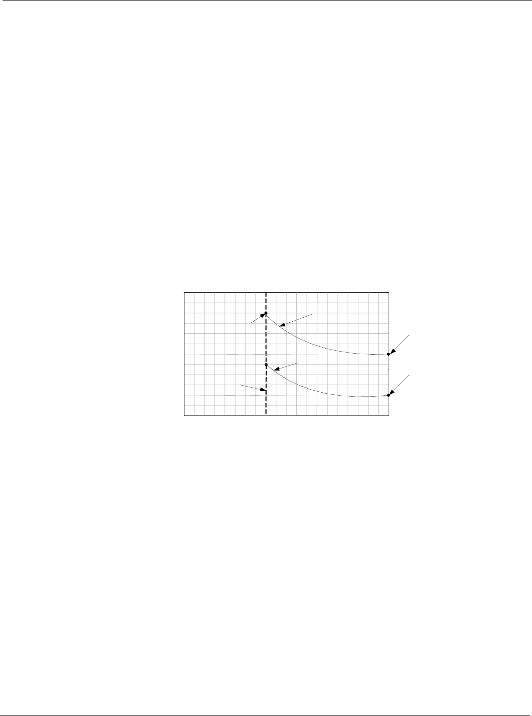
In Figure 10, the Minimum OA Position would vary linearly from 10% outside air at 0 VDC
to 100% outside air at 10 VDC. This would assume that the supply air fan speed remained at a
constant 100%. This is an example of a direct acting field supplied signal, if a reverse acting
field supplied signal is required set the OA@MinV/mA = 100% and the OA@MaxV/mA =
0%.
Figure 10: Example #2 Min OA Reset Type = EXT VDC
Outside Air Damper Control, Two Position
Two position actuators are controlled by a digital output for SCU unit and by a modulating
analog output for RTU units. These outputs are controlled differently depending on whether
the unit is a 100% OA or a Return Air.
• Digital Output - The OA damper is driven fully open when the digital output is On and fully
closed when the digital output is Off
• Analog Output (Return Air Units) - The OA damper is driven to its fully open position when
the OA damper analog output is at its maximum value and it is driven closed when the OA
damper analog output is at its minimum value. The desired minimum open position between
0% and 30% normally is set by an editable keypad menu. If a valid value is provided via the
network, that position is used as the desired minimum open position instead of the keypad
value
• Analog Output (100%OA Units) - The OA damper is driven to its 100% open position when
the OA damper analog output is at its maximum value and it is driven closed when the OA
damper analog output is at its minimum value
Vent Limit =
(Default 20%)
DCV Limit =
(Default 10%
Minimum Outdoor Air
Damper Position
Demand Control
Ventilation OA
Damper Postion
Min Clg Speed =
(Default 40%)
40%
(Minimum )
100 %
OA Damper Position %
Airflow – Min OA Type = Something
other than None
Damper Position vs. Fan Speed Chart
Lo Flow Vent Limit =
(Default 30%)