
Instruction manual


Table Of Contents
- Introduction
- Using the Keypad/Display
- Keypad/Display Menu Structure
- System Summary Menu
- Standard Menus
- System Menu
- Occupancy Menu
- Temperature Menu
- Flow Summary Menu
- Supply Fan Speed Menu
- Return/Exhaust Fan Speed Menu
- Cooling Menu
- Head Pressure Menu
- Evap Condensing Menu
- Economizer Menu
- Min OA Damper Menu
- Heating Menu
- Energy Recovery
- Dehumidification Menu
- Daily Schedule Menu
- One Event Schedule Menu
- Holiday Schedule Menu
- Optimal Start Menu
- Operating Hours Menu
- Extended Menus
- Unit Setup Menu
- Timer Settings Menu
- Time/Date Menu
- Supply Fan Setup Menu
- Return/Exhaust Fan Setup Menu
- Zone Temperature Setup Menu
- Compressor Setup Menu
- Head Pressure Setup Menu
- Chilled Water Setup Menu
- Economizer Setup Menu
- Design Flow Setup Menu
- Heating Setup Menu
- Dehumidification Setup Menu
- Alarm Out Configuration Setup Menu
- Alarm Limits Setup Menu
- Manual Control Menu
- LON/BACnetIP/BACnetMSTP Setup Menu
- Active Alarm Menu
- Alarm Log Menu
- Advanced Menus
- Unit Configuration Setup Menu
- Save/Restore Menu
- Alarm Delays Setup Menu
- Analog Input Status Menu
- Universal I/O Status Menu
- Digital Input Status Menu
- Digital Output Status Menu
- Adv Setup Settings Menu
- Adv Status Parameters Menu
- Alarms
- Operator’s Guide
- Determining Unit State
- Off Operating State
- Start Up Operating State
- Recirculating Operating State
- Heating
- Economizer
- Mechanical Cooling
- Determining Unit Status
- Determining Control Mode
- Determining Cooling Status
- Determining Heat Status
- Determining Economizer Status
- Determining Cooling Capacity
- Determining Heating Capacity
- Determining Supply Air Fan Capacity
- Determining RF/EF Capacity
- Determining Outside Air Damper Position
- Determining Emergency Mode
- Determining Application Mode
- Determining Occupancy Status
- Determining Occupancy Mode
- Determining Occupancy Source
- Unoccupied Operation
- Scheduling
- Temperature Control Configurations
- Heat/Cool Changeover
- Dehumidification
- Energy Recovery
- Outside Air Damper Control
- Outside Air Damper Control, Two Position
- Special Procedures for Units with WRV and More Than Two Circuits.
- Water Pump Control
- Cooling: Multistage
- Cooling: Modulating
- Heating Control
- Modulating
- Min DAT
- Indoor Air Fan - On/Off Control
84 McQuay OM 920
Operator’s Guide
Examples of typical Min OA reset schedules.
If IAQ VDC is selected as the Min OA Reset, the Minimum OA Position is calculated based
on a 0-10V CO2 sensor input. The CO2 level is expressed as Parts per Million. The minimum
and maximum sensor input values (0-10V) and the corresponding minimum and maximum
PPM values are user editable. This calculated Minimum OA Position varies linearly from the
Demand Control Ventilation Limit at the value labeled “PPM @ DCV Limit” to the
Ventilation Limit at the value labeled “PPM @ VentLimit”. The “PPM @ DCV Limit” is not
allow to be set equal to or greater than the “PPM @ VentLimit”.
Example #1 Min OA reset type = IAQ VDC
This example assumes a CO2 sensor with a 0-2000PPM value over a range of 0-10VDC.
If the requirement is to have the OA damper be at its minimum (DCV Limit) when the CO2
levels are less than 800PPM and to be at its maximum (Vent Limit) when the CO2 levels are
greater than 1000PPM, the controller would be set up as follow:
• Vent Limit = 100%
• DCV Limit = 10%
• Min OA reset type = IAQ VDC
• Min V/mA = 0
• Max V/mA = 10
• PPM@DCV Limit = 800
• PPM@Vent Limit = 1000
• Min PPM = 0
• Max PPM = 2000
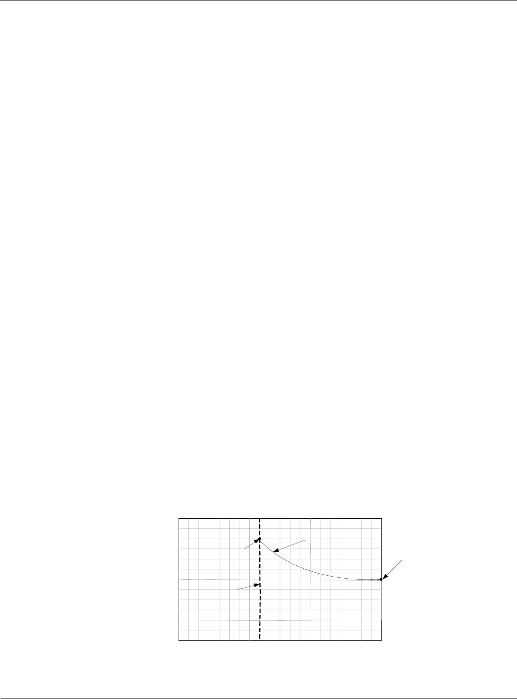
In Figure 9 the Minimum OA Position would vary linearly from 10% outside air damper
position at 800PPM or less to 100% outside air damper position at 1000PPM or greater. This
would assume that the supply air fan speed remained at a constant 100%.
If EXT VDC is selected as the Min OA Rest, the Minimum OA Position is calculated based
on an external 0-10 VDC signal. If EXT mA is selected as the Min OA Reset, the Minimum
OA Position is calculated based on an external 0-20 mA signal. This calculated Minimum OA
Position varies linearly from zero % the editable minimum external signal to 100%at the
editable maximum external signal, but it is set no lower than the Demand Control Ventilation
Limit and no higher than the Ventilation Limit. If the editable minimum external signal is set
equal to the editable maximum external signal the external reset % reverts to the Ventilation
Limit.
Figure 9: Min OA Reset Type = IAQ VDC Example
Vent Limit =
(Default 20%)
Min Clg Speed =
(Default 40%)
40%
(Minimum)
100%
OA Damper Position %
Airflow – Min OA
Type = None
Damper Position vs. Fan Speed Chart
Lo Flow Vent Limit =
(Default 30 %)