
Instruction manual


Table Of Contents
- Introduction
- Using the Keypad/Display
- Keypad/Display Menu Structure
- System Summary Menu
- Standard Menus
- System Menu
- Occupancy Menu
- Temperature Menu
- Flow Summary Menu
- Supply Fan Speed Menu
- Return/Exhaust Fan Speed Menu
- Cooling Menu
- Head Pressure Menu
- Evap Condensing Menu
- Economizer Menu
- Min OA Damper Menu
- Heating Menu
- Energy Recovery
- Dehumidification Menu
- Daily Schedule Menu
- One Event Schedule Menu
- Holiday Schedule Menu
- Optimal Start Menu
- Operating Hours Menu
- Extended Menus
- Unit Setup Menu
- Timer Settings Menu
- Time/Date Menu
- Supply Fan Setup Menu
- Return/Exhaust Fan Setup Menu
- Zone Temperature Setup Menu
- Compressor Setup Menu
- Head Pressure Setup Menu
- Chilled Water Setup Menu
- Economizer Setup Menu
- Design Flow Setup Menu
- Heating Setup Menu
- Dehumidification Setup Menu
- Alarm Out Configuration Setup Menu
- Alarm Limits Setup Menu
- Manual Control Menu
- LON/BACnetIP/BACnetMSTP Setup Menu
- Active Alarm Menu
- Alarm Log Menu
- Advanced Menus
- Unit Configuration Setup Menu
- Save/Restore Menu
- Alarm Delays Setup Menu
- Analog Input Status Menu
- Universal I/O Status Menu
- Digital Input Status Menu
- Digital Output Status Menu
- Adv Setup Settings Menu
- Adv Status Parameters Menu
- Alarms
- Operator’s Guide
- Determining Unit State
- Off Operating State
- Start Up Operating State
- Recirculating Operating State
- Heating
- Economizer
- Mechanical Cooling
- Determining Unit Status
- Determining Control Mode
- Determining Cooling Status
- Determining Heat Status
- Determining Economizer Status
- Determining Cooling Capacity
- Determining Heating Capacity
- Determining Supply Air Fan Capacity
- Determining RF/EF Capacity
- Determining Outside Air Damper Position
- Determining Emergency Mode
- Determining Application Mode
- Determining Occupancy Status
- Determining Occupancy Mode
- Determining Occupancy Source
- Unoccupied Operation
- Scheduling
- Temperature Control Configurations
- Heat/Cool Changeover
- Dehumidification
- Energy Recovery
- Outside Air Damper Control
- Outside Air Damper Control, Two Position
- Special Procedures for Units with WRV and More Than Two Circuits.
- Water Pump Control
- Cooling: Multistage
- Cooling: Modulating
- Heating Control
- Modulating
- Min DAT
- Indoor Air Fan - On/Off Control
McQuay OM 920 81
Operator’s Guide
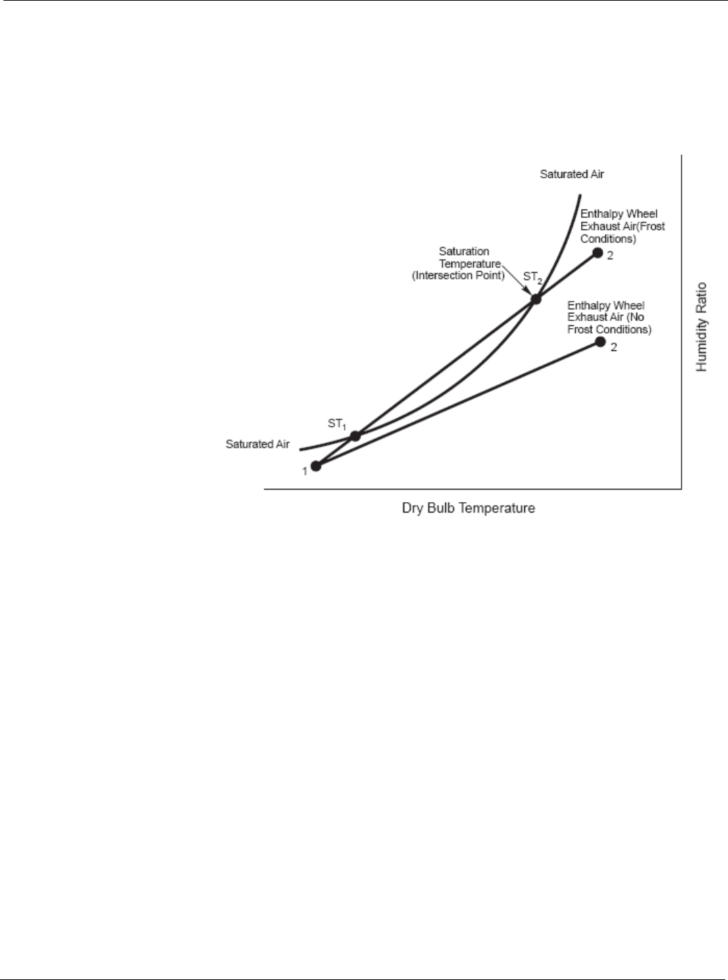
When there is a threat of frost on the enthalpy wheel, the wheel is slowed down or stopped so
that less enthalpy transfer occurs and frosting of the wheel is avoided. Frosting can occur on
the enthalpy wheel when the exhaust air leaving the wheel is saturated. This condition occurs
when two lines intersect on a psychometric chart, and it does not occur when these two lines
do not intersect. One of these lines is the Humidity Ratio versus the dry bulb temperature for
saturated air. The other line is the exhaust air process line. The exhaust air process is defined
by two points on a psychometric chart (Figure 8).
Figure 8: Exhaust Air Psychometric Chart
The first point on this line is the outdoor air temperature at 95% relative humidity (point 1 in
Figure 8) and the second point on the line is the return air temperature at the return air relative
humidity (point 2 in Figure 8). One exhaust air process line showing frosting conditions and
another showing no frost condition is shown in Figure 8. The controller makes a continuous
calculation to determine if and at what temperatures the saturated air and exhaust air process
lines intersect. When they do not intersect, the enthalpy wheel runs at full speed. When they
do intersect, the enthalpy wheel is controlled to a slower speed to maintain the dry bulb
temperature of the exhaust air leaving the enthalpy wheel above the higher of the two
intersecting dry bulb temperatures (point ST2 in Figure 8). This is referred to as the
“Intersection Point.” This prevents the wheel from operating under frosting conditions.
The following describes the details involved in the frost protection function that affect the
speed and start/stop of the enthalpy wheel:
When the enthalpy wheel has been operating at maximum speed for at least the Enthalpy
Wheel Stage Time and the exhaust air temperature leaving the wheel drops below the
Intersection Point plus the Minimum Temperature Difference, the enthalpy wheel will be
slowed to its minimum speed.
If the enthalpy wheel has been operating at minimum speed for at least the Enthalpy Wheel
Stage Time and the exhaust air temperature leaving the wheel is still below then Intersection
Point plus the Minimum Temperature Difference, the enthalpy wheel will be stopped. If the
exhaust air temperature leaving the wheel then rises above the Intersection Point plus the
Maximum Temperature Difference and the enthalpy wheel has been off for longer than the
Enthalpy Wheel Minimum Off Time, the wheel will be restarted and will run at its minimum
speed.