
Instruction manual


Table Of Contents
- Introduction
- Using the Keypad/Display
- Keypad/Display Menu Structure
- System Summary Menu
- Standard Menus
- System Menu
- Occupancy Menu
- Temperature Menu
- Flow Summary Menu
- Supply Fan Speed Menu
- Return/Exhaust Fan Speed Menu
- Cooling Menu
- Head Pressure Menu
- Evap Condensing Menu
- Economizer Menu
- Min OA Damper Menu
- Heating Menu
- Energy Recovery
- Dehumidification Menu
- Daily Schedule Menu
- One Event Schedule Menu
- Holiday Schedule Menu
- Optimal Start Menu
- Operating Hours Menu
- Extended Menus
- Unit Setup Menu
- Timer Settings Menu
- Time/Date Menu
- Supply Fan Setup Menu
- Return/Exhaust Fan Setup Menu
- Zone Temperature Setup Menu
- Compressor Setup Menu
- Head Pressure Setup Menu
- Chilled Water Setup Menu
- Economizer Setup Menu
- Design Flow Setup Menu
- Heating Setup Menu
- Dehumidification Setup Menu
- Alarm Out Configuration Setup Menu
- Alarm Limits Setup Menu
- Manual Control Menu
- LON/BACnetIP/BACnetMSTP Setup Menu
- Active Alarm Menu
- Alarm Log Menu
- Advanced Menus
- Unit Configuration Setup Menu
- Save/Restore Menu
- Alarm Delays Setup Menu
- Analog Input Status Menu
- Universal I/O Status Menu
- Digital Input Status Menu
- Digital Output Status Menu
- Adv Setup Settings Menu
- Adv Status Parameters Menu
- Alarms
- Operator’s Guide
- Determining Unit State
- Off Operating State
- Start Up Operating State
- Recirculating Operating State
- Heating
- Economizer
- Mechanical Cooling
- Determining Unit Status
- Determining Control Mode
- Determining Cooling Status
- Determining Heat Status
- Determining Economizer Status
- Determining Cooling Capacity
- Determining Heating Capacity
- Determining Supply Air Fan Capacity
- Determining RF/EF Capacity
- Determining Outside Air Damper Position
- Determining Emergency Mode
- Determining Application Mode
- Determining Occupancy Status
- Determining Occupancy Mode
- Determining Occupancy Source
- Unoccupied Operation
- Scheduling
- Temperature Control Configurations
- Heat/Cool Changeover
- Dehumidification
- Energy Recovery
- Outside Air Damper Control
- Outside Air Damper Control, Two Position
- Special Procedures for Units with WRV and More Than Two Circuits.
- Water Pump Control
- Cooling: Multistage
- Cooling: Modulating
- Heating Control
- Modulating
- Min DAT
- Indoor Air Fan - On/Off Control
McQuay OM 920 75
Operator’s Guide
Temperature Control Configurations
Temperature control is based on a Control Type that may be set to either Zone or DAT.
When the Control Type is set to Zone temperature control, heating, compressors, and the
economizer are controlled to maintain the temperature of the zone at a desired setpoint. This
configuration is used on units equipped with constant volume supply fans. Compressors and
heating stages are staged to maintain space or return temperature. The number of compressors
is decreased when it is too cold and increased when it is too hot subject to stage timers. The
number of heat stages is decreased when it is too hot and increased when it is too cold subject
to stage timers.
When the Control Type is set to DAT, heating, compressors, and the economizer are controlled
to maintain the discharge air temperature at a desired setpoint. This configuration is typically
used on units equipped with variable air volume supply fans.
Heat/Cool Changeover
In general, a unit configured for discharge air temperature control either operates to deliver the
cooling discharge temperature set point using economizer and/or mechanical cooling or the
heating discharge air temperature set point using the heating equipment. Cooling and heating
never operate simultaneously. A unit configured for zone (or space comfort) control either
operates to maintain the Zone Cooling Set Point using economizer and/or mechanical cooling
or the Zone Heating Set Point using the heating equipment.
The Zone Cooling/Zone Heating setpoints can be set via the keypad/display or based on a
signal from an optional space temperature sensor with set point adjustment capability. The
following sections describe the unit heat/ cool changeover function.
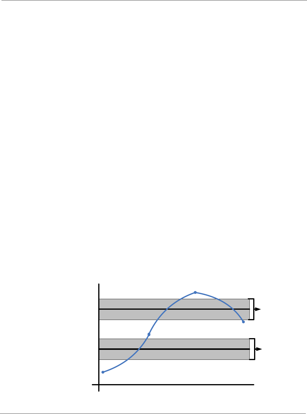
Illustrative Heat/Cool Changeover Sequence
The following is an illustration of the heat/cool changeover function.
When the Control Temperature is below the zone heating setpoint by more than ½ the
deadband (point A), heating operation is enabled. Heating operation then remains enabled
until the control temperature begins to rise and rises above the zone heating setpoint by more
than ½ the deadband (point B), at which point heating operation is disabled and the unit enters
the fan only (or Min DAT) operating state. If the control temperature rises above the zone
cooling setpoint by more than ½ the deadband (point C) cooling operation is enabled. Cooling
operation remains enabled until the control temperature begins to fall below the zone cooling
setpoint by more than ½ the deadband (point D), at which point the unit returns or fan only (or
Min DAT) operating state.
Figure 7: Heat/Cool Changeover
Heating SPT
Cooling SPT
Cooling Enabled
Heating Enabled
Fan Only
Control Temperature
Time
Clg
Db
Htg
Db
D
A
C
B