
Instruction manual


Table Of Contents
- Introduction
- Using the Keypad/Display
- Keypad/Display Menu Structure
- System Summary Menu
- Standard Menus
- System Menu
- Occupancy Menu
- Temperature Menu
- Flow Summary Menu
- Supply Fan Speed Menu
- Return/Exhaust Fan Speed Menu
- Cooling Menu
- Head Pressure Menu
- Evap Condensing Menu
- Economizer Menu
- Min OA Damper Menu
- Heating Menu
- Energy Recovery
- Dehumidification Menu
- Daily Schedule Menu
- One Event Schedule Menu
- Holiday Schedule Menu
- Optimal Start Menu
- Operating Hours Menu
- Extended Menus
- Unit Setup Menu
- Timer Settings Menu
- Time/Date Menu
- Supply Fan Setup Menu
- Return/Exhaust Fan Setup Menu
- Zone Temperature Setup Menu
- Compressor Setup Menu
- Head Pressure Setup Menu
- Chilled Water Setup Menu
- Economizer Setup Menu
- Design Flow Setup Menu
- Heating Setup Menu
- Dehumidification Setup Menu
- Alarm Out Configuration Setup Menu
- Alarm Limits Setup Menu
- Manual Control Menu
- LON/BACnetIP/BACnetMSTP Setup Menu
- Active Alarm Menu
- Alarm Log Menu
- Advanced Menus
- Unit Configuration Setup Menu
- Save/Restore Menu
- Alarm Delays Setup Menu
- Analog Input Status Menu
- Universal I/O Status Menu
- Digital Input Status Menu
- Digital Output Status Menu
- Adv Setup Settings Menu
- Adv Status Parameters Menu
- Alarms
- Operator’s Guide
- Determining Unit State
- Off Operating State
- Start Up Operating State
- Recirculating Operating State
- Heating
- Economizer
- Mechanical Cooling
- Determining Unit Status
- Determining Control Mode
- Determining Cooling Status
- Determining Heat Status
- Determining Economizer Status
- Determining Cooling Capacity
- Determining Heating Capacity
- Determining Supply Air Fan Capacity
- Determining RF/EF Capacity
- Determining Outside Air Damper Position
- Determining Emergency Mode
- Determining Application Mode
- Determining Occupancy Status
- Determining Occupancy Mode
- Determining Occupancy Source
- Unoccupied Operation
- Scheduling
- Temperature Control Configurations
- Heat/Cool Changeover
- Dehumidification
- Energy Recovery
- Outside Air Damper Control
- Outside Air Damper Control, Two Position
- Special Procedures for Units with WRV and More Than Two Circuits.
- Water Pump Control
- Cooling: Multistage
- Cooling: Modulating
- Heating Control
- Modulating
- Min DAT
- Indoor Air Fan - On/Off Control
48 McQuay OM 920
Keypad/Display Menu Structure
Advanced Menus
The Advanced Menus should only be accessed by trained service personnel.
The Advanced Menus are menu items that are used to set up the unit for its specific
application. Accessing the Advanced Menus requires the operator to enter the four-digit level
2 password, (6363) using the keypad buttons located on the controller interface.
The following Menu items are meant to be used as a set up and/or troubleshooting tool and
should only be accesses by trained Service Technicians.
Unit Configuration Setup Menu
After the main control board application software is loaded into the MCB, it must be
“configured” for the specific control application. This consists of setting the value of 23
configuration variables within the MCB. These variables define things such as the type of
cooling, number of compressors and cooling stages and the type of heat. If all of these items
are not set appropriately for the specific unit, the unit will not function properly. The correct
settings for these parameters are defined for a given unit by the unit “Software Configuration
Code.”
The “Software Configuration Code” consists of a 26-character string of numbers and letters.
The code can be found on the Unit Software Identification Label located on the back side of
the control panel door. Only the first 23 characters of this code are used for software
configuration purposes.
The table shown on page ***(revise) lists the configuration code variables including the
position within the code, description of the parameter, and the applicable settings for each. The
default values are shown in bold font. The unit is configured at the factory however may also
be configured in the field by accessing the Unit Configuration Menu. Once changes have been
made to the Unit Configuration Menu, the Apply Changes flag must be changed from no to
yes in order for the controller to recognize the changes. Setting the Apply Changes flag to
YES will automatically rest the controller.
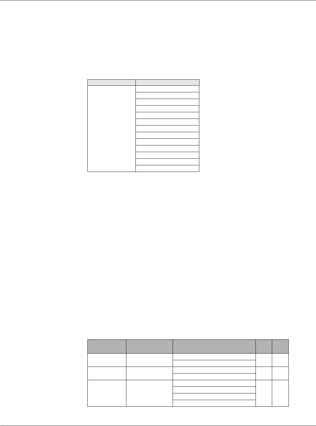
Table 42: Advanced Menus
Menu Display Name Item Display Name
Advanced Menus Unit Configuration
Save/Restore
LON Setup
BACnet MSTP Setup
BACnet IP Setup
Alarm Delays
Network Variables
Analog Input Status
Universal I/O Status
Digital Input Status
Digital Output Status
Adv Setup Settings
Adv Status Params
Table 43: Unit Configuration Menu
Configuration
Code Position
Description Values (Default Bold) RTU SCU
1 Unit Type 0 = Rooftop (RTU) • •
1 = Self-Contained (SCU)
2 Control Type 0 = Zone Control • •
1 = DAT Control
3 Cooling Type 0 = None • •
1 = Compressorized Clg
2 = Chilled Water
3 = F&BP