
Instruction manual


Table Of Contents
- Introduction
- Using the Keypad/Display
- Keypad/Display Menu Structure
- System Summary Menu
- Standard Menus
- System Menu
- Occupancy Menu
- Temperature Menu
- Flow Summary Menu
- Supply Fan Speed Menu
- Return/Exhaust Fan Speed Menu
- Cooling Menu
- Head Pressure Menu
- Evap Condensing Menu
- Economizer Menu
- Min OA Damper Menu
- Heating Menu
- Energy Recovery
- Dehumidification Menu
- Daily Schedule Menu
- One Event Schedule Menu
- Holiday Schedule Menu
- Optimal Start Menu
- Operating Hours Menu
- Extended Menus
- Unit Setup Menu
- Timer Settings Menu
- Time/Date Menu
- Supply Fan Setup Menu
- Return/Exhaust Fan Setup Menu
- Zone Temperature Setup Menu
- Compressor Setup Menu
- Head Pressure Setup Menu
- Chilled Water Setup Menu
- Economizer Setup Menu
- Design Flow Setup Menu
- Heating Setup Menu
- Dehumidification Setup Menu
- Alarm Out Configuration Setup Menu
- Alarm Limits Setup Menu
- Manual Control Menu
- LON/BACnetIP/BACnetMSTP Setup Menu
- Active Alarm Menu
- Alarm Log Menu
- Advanced Menus
- Unit Configuration Setup Menu
- Save/Restore Menu
- Alarm Delays Setup Menu
- Analog Input Status Menu
- Universal I/O Status Menu
- Digital Input Status Menu
- Digital Output Status Menu
- Adv Setup Settings Menu
- Adv Status Parameters Menu
- Alarms
- Operator’s Guide
- Determining Unit State
- Off Operating State
- Start Up Operating State
- Recirculating Operating State
- Heating
- Economizer
- Mechanical Cooling
- Determining Unit Status
- Determining Control Mode
- Determining Cooling Status
- Determining Heat Status
- Determining Economizer Status
- Determining Cooling Capacity
- Determining Heating Capacity
- Determining Supply Air Fan Capacity
- Determining RF/EF Capacity
- Determining Outside Air Damper Position
- Determining Emergency Mode
- Determining Application Mode
- Determining Occupancy Status
- Determining Occupancy Mode
- Determining Occupancy Source
- Unoccupied Operation
- Scheduling
- Temperature Control Configurations
- Heat/Cool Changeover
- Dehumidification
- Energy Recovery
- Outside Air Damper Control
- Outside Air Damper Control, Two Position
- Special Procedures for Units with WRV and More Than Two Circuits.
- Water Pump Control
- Cooling: Multistage
- Cooling: Modulating
- Heating Control
- Modulating
- Min DAT
- Indoor Air Fan - On/Off Control
McQuay OM 920 47
Keypad/Display Menu Structure
LON/BACnetIP/BACnetMSTP Setup Menu
See the Installation & Maintenance Manuals below for detailed instructions
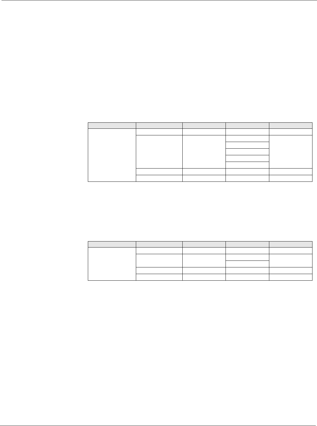
Active Alarm Menu
All active alarms as well as the date and time that they were detected are displayed on the
Active Alarm menu. These alarms are displayed in order of group priority: Faults first,
Problems second, and Warnings last. Within each group, alarms are displayed in the order
that they were detected.
Alarm Log Menu
The last fifty alarms detected as well as the date and times that they were detected are
displayed on the Alarm Log menu. These alarms are displayed in the order that they were
detected. The alarm that was detected most recently is displayed first. Multiple occurrences of
the same alarm may appear.
Note – Once an alarm is cleared there will be two entries in the Alarm Log. A (+) sign will be
shown next to the entry added when the alarm became active and a (-) sign will be shown
next to the entry added when the alarm has been cleared.
IM 916 MicroTech III Rooftop unit controller - BACnet IP communications
IM 917 MicroTech III Rooftop unit controller - BACnet MSTP communications
IM 918 MicroTech III Rooftop unit controller - BACnet LON communications
Table 40: Active Alarm Menu
Menu Display Name Item Display Name Default Setting Range Password Level
Active Alarms Active Alm Count= - 0-10 None
ClrAlms= No No None
ClrFlts
ClrPrblms
ClrWrngs
ClrAllAlms
+Alarm 1:Alarm Type - None
+Alarm 2:Alarm Type - None
Table 41: Alarm Log Menu
Menu Display Name Item Display Name Default Setting Range Password Level
Alarm Log Log Alm Count= - 0-50 None
ClrLog= No No None
Yes
+Alarm 1:Alarm Type - None
+Alarm 2:Alarm Type - None