
Instruction manual


Table Of Contents
- Introduction
- Using the Keypad/Display
- Keypad/Display Menu Structure
- System Summary Menu
- Standard Menus
- System Menu
- Occupancy Menu
- Temperature Menu
- Flow Summary Menu
- Supply Fan Speed Menu
- Return/Exhaust Fan Speed Menu
- Cooling Menu
- Head Pressure Menu
- Evap Condensing Menu
- Economizer Menu
- Min OA Damper Menu
- Heating Menu
- Energy Recovery
- Dehumidification Menu
- Daily Schedule Menu
- One Event Schedule Menu
- Holiday Schedule Menu
- Optimal Start Menu
- Operating Hours Menu
- Extended Menus
- Unit Setup Menu
- Timer Settings Menu
- Time/Date Menu
- Supply Fan Setup Menu
- Return/Exhaust Fan Setup Menu
- Zone Temperature Setup Menu
- Compressor Setup Menu
- Head Pressure Setup Menu
- Chilled Water Setup Menu
- Economizer Setup Menu
- Design Flow Setup Menu
- Heating Setup Menu
- Dehumidification Setup Menu
- Alarm Out Configuration Setup Menu
- Alarm Limits Setup Menu
- Manual Control Menu
- LON/BACnetIP/BACnetMSTP Setup Menu
- Active Alarm Menu
- Alarm Log Menu
- Advanced Menus
- Unit Configuration Setup Menu
- Save/Restore Menu
- Alarm Delays Setup Menu
- Analog Input Status Menu
- Universal I/O Status Menu
- Digital Input Status Menu
- Digital Output Status Menu
- Adv Setup Settings Menu
- Adv Status Parameters Menu
- Alarms
- Operator’s Guide
- Determining Unit State
- Off Operating State
- Start Up Operating State
- Recirculating Operating State
- Heating
- Economizer
- Mechanical Cooling
- Determining Unit Status
- Determining Control Mode
- Determining Cooling Status
- Determining Heat Status
- Determining Economizer Status
- Determining Cooling Capacity
- Determining Heating Capacity
- Determining Supply Air Fan Capacity
- Determining RF/EF Capacity
- Determining Outside Air Damper Position
- Determining Emergency Mode
- Determining Application Mode
- Determining Occupancy Status
- Determining Occupancy Mode
- Determining Occupancy Source
- Unoccupied Operation
- Scheduling
- Temperature Control Configurations
- Heat/Cool Changeover
- Dehumidification
- Energy Recovery
- Outside Air Damper Control
- Outside Air Damper Control, Two Position
- Special Procedures for Units with WRV and More Than Two Circuits.
- Water Pump Control
- Cooling: Multistage
- Cooling: Modulating
- Heating Control
- Modulating
- Min DAT
- Indoor Air Fan - On/Off Control
McQuay OM 920 45
Keypad/Display Menu Structure
Manual Ctrl is an adjustable item that puts the unit into manual control. Major components of
the unit are turned on and off by this control. The units normal control sequences are
overridden in this state with the exception of all the “fault” alarms and the cooling circuit high
pressure and low pressure alarms.
Supply Fan is an adjustable item that turns on the supply fan.
RF/EF is an adjustable item that turns on the return/exhaust fan.
SAF Spd Cmd is an adjustable item only on VAV units that sets the speed of the supply air
fan.
RF/EF Spd Cmd is an adjustable item for units with VFD on the return/exhaust fans that set
the speed of the return/exhaust fan.
OAD/Econo is an adjustable item which is used to set the economizer damper position.
OAD OpCl is an adjustable item which is used to turn the OA damper output on. This output
is available only on self contained units.
Comp 1 OnOff is an adjustable item that turns on compressor #1.
Comp 2 OnOff is an adjustable item that turns on compressor #2.
Comp 3 OnOff is an adjustable item that turns on compressor #3.
Comp 4 OnOff is an adjustable item that turns on compressor #4.
Comp 5 OnOff is an adjustable item that turns on compressor #5.
Comp 6 OnOff is an adjustable item that turns on compressor #6.
Comp 7 OnOff is an adjustable item that turns on compressor #7.
Comp 8 OnOff is an adjustable item that turns on compressor #8.
CFan Outpt 1 an adjustable item that turns on the condenser fan output #1.
CFan Outpt 2 an adjustable item that turns on the condenser fan output #2.
CFan Outpt 3 an adjustable item that turns on the condenser fan output #3.
Note – Turning on any one of the compressors will automatically turn on the first condenser fan on
the circuit. Other condenser fans must be manually turned on to control the head pressure
of the unit. Refrigerant gauges must be connected to the unit for observation of the head
pressure in the manual control mode of operation. Additional condenser fans must be
turned on to maintain the head pressure.
BP/WR Valve is an adjustable item used to manually drive the bypass/water regulating valve
open and closed.
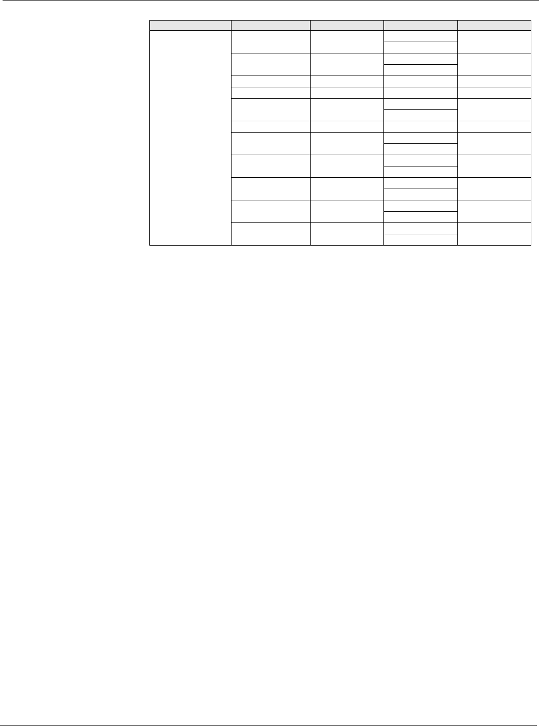
Manual Control Htg Stg 5= Off Off 4
On
Htg Stg 6= Off Off 4
On
Reheat Valve= 0% 0-100% 4
Reheat Stage= Off Off 4
ERec Wheel= Off Off 4
On
ER Whl Cmd= 0% 0-100% 4
ERBP Dmpr Cl= Off Off 4
On
ERBP Dmpr Op= Off Off 4
On
Cond Wtr Pump= Off Off 4
On
Alm Output= Off Off 4
On
FanOp= Off Off 4
On
Table 39: Manual Control Manual
Menu Display Name Item Display Name Default Setting Range Password Level