
Instruction manual


Table Of Contents
- Introduction
- Using the Keypad/Display
- Keypad/Display Menu Structure
- System Summary Menu
- Standard Menus
- System Menu
- Occupancy Menu
- Temperature Menu
- Flow Summary Menu
- Supply Fan Speed Menu
- Return/Exhaust Fan Speed Menu
- Cooling Menu
- Head Pressure Menu
- Evap Condensing Menu
- Economizer Menu
- Min OA Damper Menu
- Heating Menu
- Energy Recovery
- Dehumidification Menu
- Daily Schedule Menu
- One Event Schedule Menu
- Holiday Schedule Menu
- Optimal Start Menu
- Operating Hours Menu
- Extended Menus
- Unit Setup Menu
- Timer Settings Menu
- Time/Date Menu
- Supply Fan Setup Menu
- Return/Exhaust Fan Setup Menu
- Zone Temperature Setup Menu
- Compressor Setup Menu
- Head Pressure Setup Menu
- Chilled Water Setup Menu
- Economizer Setup Menu
- Design Flow Setup Menu
- Heating Setup Menu
- Dehumidification Setup Menu
- Alarm Out Configuration Setup Menu
- Alarm Limits Setup Menu
- Manual Control Menu
- LON/BACnetIP/BACnetMSTP Setup Menu
- Active Alarm Menu
- Alarm Log Menu
- Advanced Menus
- Unit Configuration Setup Menu
- Save/Restore Menu
- Alarm Delays Setup Menu
- Analog Input Status Menu
- Universal I/O Status Menu
- Digital Input Status Menu
- Digital Output Status Menu
- Adv Setup Settings Menu
- Adv Status Parameters Menu
- Alarms
- Operator’s Guide
- Determining Unit State
- Off Operating State
- Start Up Operating State
- Recirculating Operating State
- Heating
- Economizer
- Mechanical Cooling
- Determining Unit Status
- Determining Control Mode
- Determining Cooling Status
- Determining Heat Status
- Determining Economizer Status
- Determining Cooling Capacity
- Determining Heating Capacity
- Determining Supply Air Fan Capacity
- Determining RF/EF Capacity
- Determining Outside Air Damper Position
- Determining Emergency Mode
- Determining Application Mode
- Determining Occupancy Status
- Determining Occupancy Mode
- Determining Occupancy Source
- Unoccupied Operation
- Scheduling
- Temperature Control Configurations
- Heat/Cool Changeover
- Dehumidification
- Energy Recovery
- Outside Air Damper Control
- Outside Air Damper Control, Two Position
- Special Procedures for Units with WRV and More Than Two Circuits.
- Water Pump Control
- Cooling: Multistage
- Cooling: Modulating
- Heating Control
- Modulating
- Min DAT
- Indoor Air Fan - On/Off Control
McQuay OM 920 41
Keypad/Display Menu Structure
Dehumidification Setup Menu
RH DB is an adjustable item that sets a dead band around the relative humidity set point. For
example, if the RH Setpoint parameter is set to 50% and the RH Db parameter is set to 2% the
dead band around the set point would be from 49% to 51%.
Dewpoint DB is an adjustable item that sets a dead band around the dew point set point. For
example, if the DewPoint Spt parameter is set to 50ºF and the DewPntDb parameter is set to
2ºF the dead band around the set point would be from 49ºF to 51ºF.
Dehum Method is an adjustable item used to select whether dehumidification operation is
based on relative humidity or dew point.
Dehum Ctrl is an adjustable item used to select whether dehumidification as “always”
allowed or only during “occupied” modes of operation.
Sensor Loc is an adjustable item which is used to select the location of the humidity sensor.
The location is selected by setting the Sensor Location value on the keypad to Return, Space,
or OAT. The significance of the sensor location is that this determines which temperature
sensor is use to calculate the Dewpoint. OAT can only be selected for units with DAT control.
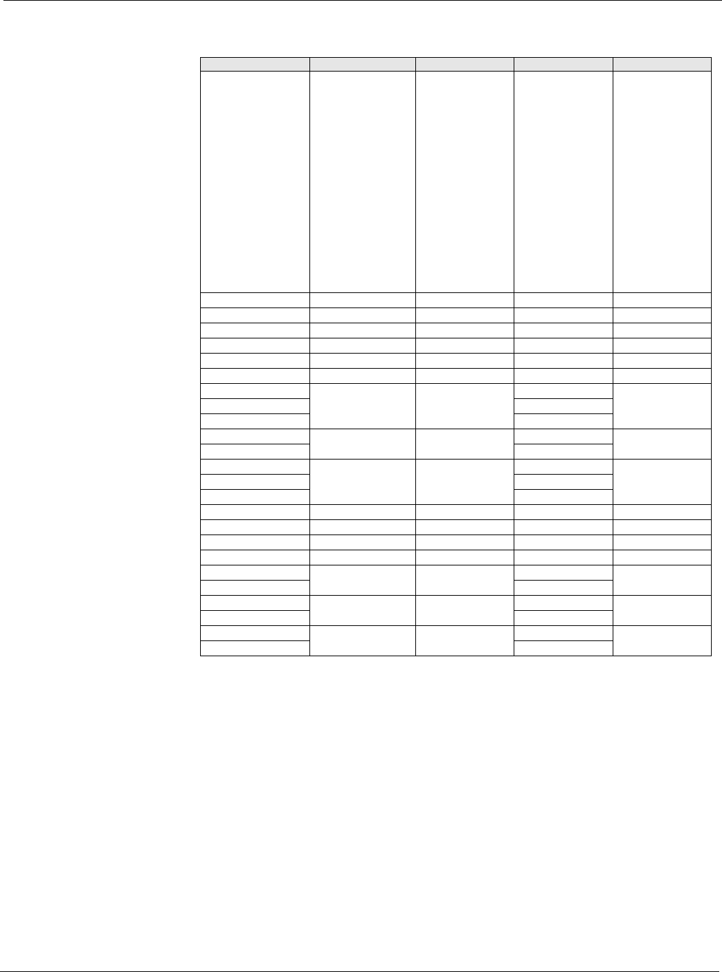
Table 36: Dehumidification Setup Menu
Menu Display Name Item Display Name Default Setting Range Password Level
Dehum Setup RH DB= 2% 0-10% 4
Dewpoint DB= 2°F 2-10°F 4
Reheat Period= 10s 0-999s 4
Reheat Gain= 1 0.0-100.0 4
Reheat PAT= 20s 0-999s 4
RH Max Chg= 16% 0-100% 4
RH Stg Time= 10 0-60m 4
Dehum Method= None None 4
Rel Hum
DewPt
Dehum Ctrl= Occupied Occupied 4
Always
Sensor Loc= Return Return 4
Space
OAT
Mn Lvg Coil T= 48.0°F 4
Mx Lvg Coil T= 55.0°F 4
Min Rheat Spt= 55.0°F 40.0-100.0°F 4
Max Rheat Spt = 65.0°F 40.0-100.0°F 4
RH Sens Type= VDC VDC 4
mA
RH Min Signal= 0.0V 0.0-20.0 4
V/mA
RH Max Signal= 10.0V 0.0-20.0 4
V/mA