
Instruction manual


Table Of Contents
- Introduction
- Using the Keypad/Display
- Keypad/Display Menu Structure
- System Summary Menu
- Standard Menus
- System Menu
- Occupancy Menu
- Temperature Menu
- Flow Summary Menu
- Supply Fan Speed Menu
- Return/Exhaust Fan Speed Menu
- Cooling Menu
- Head Pressure Menu
- Evap Condensing Menu
- Economizer Menu
- Min OA Damper Menu
- Heating Menu
- Energy Recovery
- Dehumidification Menu
- Daily Schedule Menu
- One Event Schedule Menu
- Holiday Schedule Menu
- Optimal Start Menu
- Operating Hours Menu
- Extended Menus
- Unit Setup Menu
- Timer Settings Menu
- Time/Date Menu
- Supply Fan Setup Menu
- Return/Exhaust Fan Setup Menu
- Zone Temperature Setup Menu
- Compressor Setup Menu
- Head Pressure Setup Menu
- Chilled Water Setup Menu
- Economizer Setup Menu
- Design Flow Setup Menu
- Heating Setup Menu
- Dehumidification Setup Menu
- Alarm Out Configuration Setup Menu
- Alarm Limits Setup Menu
- Manual Control Menu
- LON/BACnetIP/BACnetMSTP Setup Menu
- Active Alarm Menu
- Alarm Log Menu
- Advanced Menus
- Unit Configuration Setup Menu
- Save/Restore Menu
- Alarm Delays Setup Menu
- Analog Input Status Menu
- Universal I/O Status Menu
- Digital Input Status Menu
- Digital Output Status Menu
- Adv Setup Settings Menu
- Adv Status Parameters Menu
- Alarms
- Operator’s Guide
- Determining Unit State
- Off Operating State
- Start Up Operating State
- Recirculating Operating State
- Heating
- Economizer
- Mechanical Cooling
- Determining Unit Status
- Determining Control Mode
- Determining Cooling Status
- Determining Heat Status
- Determining Economizer Status
- Determining Cooling Capacity
- Determining Heating Capacity
- Determining Supply Air Fan Capacity
- Determining RF/EF Capacity
- Determining Outside Air Damper Position
- Determining Emergency Mode
- Determining Application Mode
- Determining Occupancy Status
- Determining Occupancy Mode
- Determining Occupancy Source
- Unoccupied Operation
- Scheduling
- Temperature Control Configurations
- Heat/Cool Changeover
- Dehumidification
- Energy Recovery
- Outside Air Damper Control
- Outside Air Damper Control, Two Position
- Special Procedures for Units with WRV and More Than Two Circuits.
- Water Pump Control
- Cooling: Multistage
- Cooling: Modulating
- Heating Control
- Modulating
- Min DAT
- Indoor Air Fan - On/Off Control
40 McQuay OM 920
Keypad/Display Menu Structure
Heating Setup Menu
Htg DB is an adjustable item which sets a dead band around the discharge heating setpoint
parameter. For example, if the discharge heating setpoint parameter is set to 100ºF and the Htg
Db= parameter is set to 2ºF, the dead band around the set point would be from 101.0ºF to
99.0ºF.
Htg Period an adjustable item which sets the “sampling time” used in the PI control function
that modulates the heating valve.
Htg Gain is an adjustable item which sets the “proportional band” used in the PI control
function that modulates the heating valve.
Htg PAT is an adjustable item which sets the “project ahead” used in the PI control function
that modulates the heating valve.
Htg Max Chg is an adjustable item that sets the maximum value for an increase or decrease of
the heating valve position.
Stage Time is an adjustable item used to set a minimum time period between heating stage
changes.
OAT Htg Lock is an adjustable item which sets the high outdoor air temperature heating
lockout point. Heating operation is disabled when the outdoor air temperature sensor input
rises above this set point.
OAT Diff is an adjustable item which sets a differential below the OATHtg Lock parameter.
Heating operation is re-enabled when the outdoor air temperature sensor input falls below the
OATHtg Lock value by more than this differential.
F&BP Method is an adjustable item used to set the face and bypass control method. When a
unit equipped with steam or hot water and face and bypass damper, there are two methods
available for controlling the heating arrangement. These are the “Open Valve” and
“Modulating Valve” methods.
F&BP ChgOvrT is an adjustable item used to set the face and bypass changeover
temperature.
Warmup Period is an adjustable item which is used to set the amount of time the gas burner
will remain at a low fire position on 100% OSA units (default 240 seconds).
Heat Up Delay is an adjustable item which is used to set the amount of time the burner will
spend at its calculated position in order to heat up the heat exchanger prior to starting the fans
(default 60 seconds)on 100% OA units. Proper setting will result in discharge temperature that
is slightly above the low discharge alarm setting upon start up.
Hold Period is an adjustable item used to set the amount of time that the gas heating valve
remains at its calculated value on units equipped with 100% OA (default 240 seconds). This is
to allow the temperature to approach equilibrium with the modulating gas heating valve at a
fixed position.
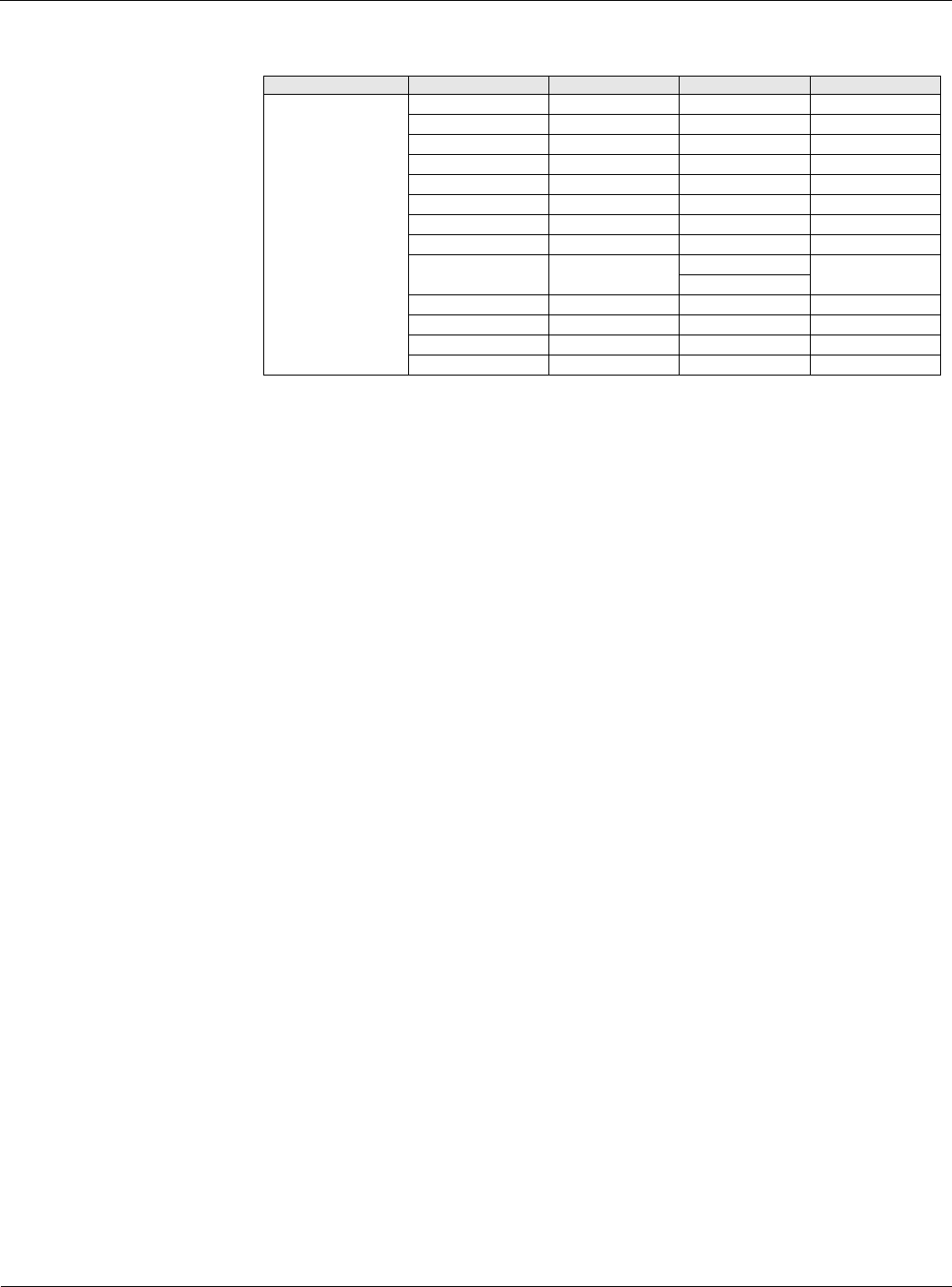
Table 35: Heating Setup Menu
Menu Display Name Item Display Name Default Setting Range Password Level
Heating Setup Htg DB= 2.0d°F 1.0-10.0°F 4
Htg Period= 60s 0-999s 4
Htg Gain= 0.8 0.0-100.0 4
Htg PAT= 120s 0-999s 4
Htg Max Chg= 10% 0-100% 4
Stage Time= 5min 2-60min 4
OAT Htg Lock= 55°F 0-100°F 4
OAT Diff= 2d°F 0-10°F 4
F&BP Method= OpenVlv OpenVlv 4
ModVlv
F&BP ChgOvrT= 37°F 0-60°F 4
Warmup Period= 240s 0-999s 4
Heat Up Delay= 60s 0-999s 4
Hold Period= 240s 0-999s 4