
Instruction manual


Table Of Contents
- Introduction
- Using the Keypad/Display
- Keypad/Display Menu Structure
- System Summary Menu
- Standard Menus
- System Menu
- Occupancy Menu
- Temperature Menu
- Flow Summary Menu
- Supply Fan Speed Menu
- Return/Exhaust Fan Speed Menu
- Cooling Menu
- Head Pressure Menu
- Evap Condensing Menu
- Economizer Menu
- Min OA Damper Menu
- Heating Menu
- Energy Recovery
- Dehumidification Menu
- Daily Schedule Menu
- One Event Schedule Menu
- Holiday Schedule Menu
- Optimal Start Menu
- Operating Hours Menu
- Extended Menus
- Unit Setup Menu
- Timer Settings Menu
- Time/Date Menu
- Supply Fan Setup Menu
- Return/Exhaust Fan Setup Menu
- Zone Temperature Setup Menu
- Compressor Setup Menu
- Head Pressure Setup Menu
- Chilled Water Setup Menu
- Economizer Setup Menu
- Design Flow Setup Menu
- Heating Setup Menu
- Dehumidification Setup Menu
- Alarm Out Configuration Setup Menu
- Alarm Limits Setup Menu
- Manual Control Menu
- LON/BACnetIP/BACnetMSTP Setup Menu
- Active Alarm Menu
- Alarm Log Menu
- Advanced Menus
- Unit Configuration Setup Menu
- Save/Restore Menu
- Alarm Delays Setup Menu
- Analog Input Status Menu
- Universal I/O Status Menu
- Digital Input Status Menu
- Digital Output Status Menu
- Adv Setup Settings Menu
- Adv Status Parameters Menu
- Alarms
- Operator’s Guide
- Determining Unit State
- Off Operating State
- Start Up Operating State
- Recirculating Operating State
- Heating
- Economizer
- Mechanical Cooling
- Determining Unit Status
- Determining Control Mode
- Determining Cooling Status
- Determining Heat Status
- Determining Economizer Status
- Determining Cooling Capacity
- Determining Heating Capacity
- Determining Supply Air Fan Capacity
- Determining RF/EF Capacity
- Determining Outside Air Damper Position
- Determining Emergency Mode
- Determining Application Mode
- Determining Occupancy Status
- Determining Occupancy Mode
- Determining Occupancy Source
- Unoccupied Operation
- Scheduling
- Temperature Control Configurations
- Heat/Cool Changeover
- Dehumidification
- Energy Recovery
- Outside Air Damper Control
- Outside Air Damper Control, Two Position
- Special Procedures for Units with WRV and More Than Two Circuits.
- Water Pump Control
- Cooling: Multistage
- Cooling: Modulating
- Heating Control
- Modulating
- Min DAT
- Indoor Air Fan - On/Off Control
4 McQuay OM 920
Introduction
Introduction
This manual provides information regarding the MicroTech III control system. It specifically
describes the operation and programmable options for units with constant air volume (CAV)
control and variable air volume (VAV) control.
The MicroTech III Controller is a self contained device that is capable of complete, stand-
alone operation. Information in the controller can be displayed and modified by using the
keypad/display in the units main control panel. For installation and startup instructions and
general information regarding a particular unit, refer to the applicable model-specific
installation and maintenance manual.
For installation and startup instructions and general information regarding a particular rooftop
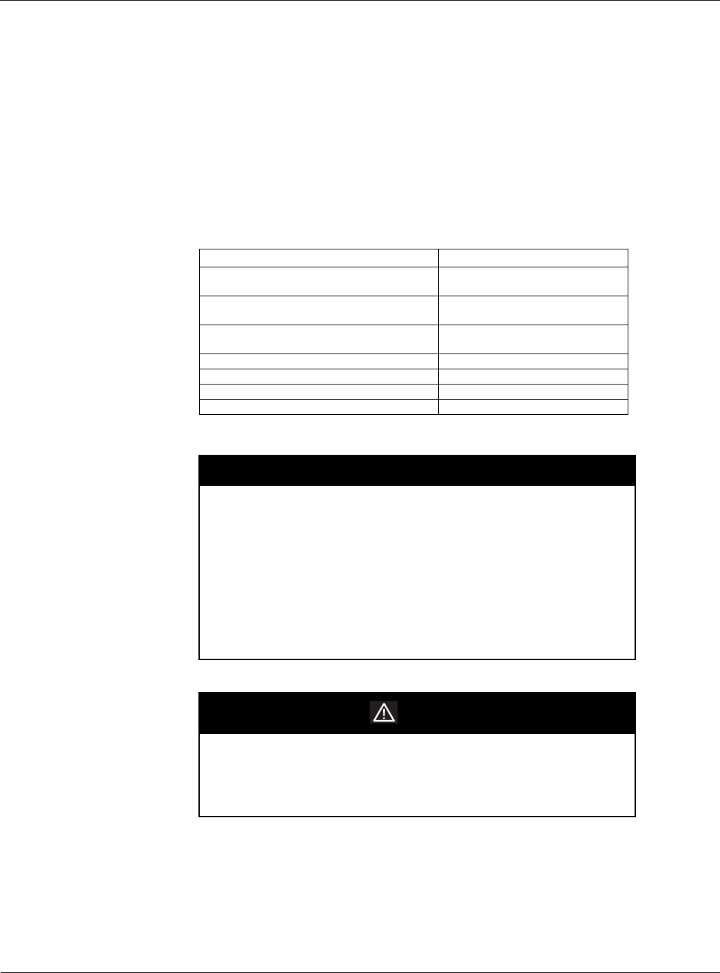
unit, refer to the applicable model-specific installation and maintenance manual (Table 1).
Table 1: Installation and Maintenance Resources
Unit Manual
MicroTech III Rooftop Unit Controller - BACnet IP
Communications
IM 916
MicroTech III Rooftop Unit Controller - BACnet
MSTP Communications
IM 917
MicroTech III Rooftop Unit Controller - BACnet
LON Communications
IM 918
MicroTech III Unit Controller IM 919
RPS/RDT/RFS/RCS 015C-105C IM 926
RPS/RDT/RFS/RCS 050D-140D IM 893
SWP Self-Contained (018 to 105) IM 937
NOTICE
This equipment generates, uses, and can radiate radio frequency energy and,
if not installed and used in accordance with this instruction manual, may cause
interference to radio communications. It has been tested and found to comply
with the limits for a Class A digital device, pursuant to part 15 of the FCC rules.
These limits are designed to provide reasonable protection against harmful
interference when the equipment is operated in a commercial environment.
Operation of this equipment in a residential area is likely to cause harmful
interference in which case the user is required to correct the interference at his
own expense. McQuay International disclaims any liability resulting from
any interference or for the correction thereof.
WARNING
Electric shock hazard. Can cause personal injury or equipment damage.
This equipment must be properly grounded. Connections and service to the
MicroTech II control panel must be performed only by personnel that are
knowledgeable in the operation of the equipment being controlled.