
Instruction manual


Table Of Contents
- Introduction
- Using the Keypad/Display
- Keypad/Display Menu Structure
- System Summary Menu
- Standard Menus
- System Menu
- Occupancy Menu
- Temperature Menu
- Flow Summary Menu
- Supply Fan Speed Menu
- Return/Exhaust Fan Speed Menu
- Cooling Menu
- Head Pressure Menu
- Evap Condensing Menu
- Economizer Menu
- Min OA Damper Menu
- Heating Menu
- Energy Recovery
- Dehumidification Menu
- Daily Schedule Menu
- One Event Schedule Menu
- Holiday Schedule Menu
- Optimal Start Menu
- Operating Hours Menu
- Extended Menus
- Unit Setup Menu
- Timer Settings Menu
- Time/Date Menu
- Supply Fan Setup Menu
- Return/Exhaust Fan Setup Menu
- Zone Temperature Setup Menu
- Compressor Setup Menu
- Head Pressure Setup Menu
- Chilled Water Setup Menu
- Economizer Setup Menu
- Design Flow Setup Menu
- Heating Setup Menu
- Dehumidification Setup Menu
- Alarm Out Configuration Setup Menu
- Alarm Limits Setup Menu
- Manual Control Menu
- LON/BACnetIP/BACnetMSTP Setup Menu
- Active Alarm Menu
- Alarm Log Menu
- Advanced Menus
- Unit Configuration Setup Menu
- Save/Restore Menu
- Alarm Delays Setup Menu
- Analog Input Status Menu
- Universal I/O Status Menu
- Digital Input Status Menu
- Digital Output Status Menu
- Adv Setup Settings Menu
- Adv Status Parameters Menu
- Alarms
- Operator’s Guide
- Determining Unit State
- Off Operating State
- Start Up Operating State
- Recirculating Operating State
- Heating
- Economizer
- Mechanical Cooling
- Determining Unit Status
- Determining Control Mode
- Determining Cooling Status
- Determining Heat Status
- Determining Economizer Status
- Determining Cooling Capacity
- Determining Heating Capacity
- Determining Supply Air Fan Capacity
- Determining RF/EF Capacity
- Determining Outside Air Damper Position
- Determining Emergency Mode
- Determining Application Mode
- Determining Occupancy Status
- Determining Occupancy Mode
- Determining Occupancy Source
- Unoccupied Operation
- Scheduling
- Temperature Control Configurations
- Heat/Cool Changeover
- Dehumidification
- Energy Recovery
- Outside Air Damper Control
- Outside Air Damper Control, Two Position
- Special Procedures for Units with WRV and More Than Two Circuits.
- Water Pump Control
- Cooling: Multistage
- Cooling: Modulating
- Heating Control
- Modulating
- Min DAT
- Indoor Air Fan - On/Off Control
McQuay OM 920 39
Keypad/Display Menu Structure
Econo Max Chg is an adjustable item that sets the maximum value for an increase or decrease
of the economizer actuator.
Flush Econo is an adjustable item used to initiate the waterside economizer flush mode
sequence.
Econo Diff is an adjustable item which sets a differential above the EconChgovrT parameter.
Economizer operation is disabled when the OA Temp parameter indicates a value above the
EconChgovrT= parameter by more than this differential.
Design Flow Setup Menu
Des Flo DB is an adjustable item which sets the “deadband” used in the control function that
modulates Min OA Pos parameter to maintain the OA Flow parameter at the MinOA Flow set
point when a unit is equipped with the optional DesignFlow outdoor airflow measuring
feature.
DF Period is an adjustable item which sets the “sampling time” used in the PI control function
that modulates the Min OA Pos parameter to maintain the OA Flow parameter at the MinOA
Flow set point when a unit is equipped with the optional DesignFlow outdoor airflow
measuring feature.
Des Flo Gain is an adjustable item which sets the “proportional band” used in the PI control
function that modulates the Min OA Pos parameter to maintain the OA Flow parameter at the
MinOA Flow set point when a unit is equipped with the optional DesignFlow outdoor airflow
measuring feature.
Des Flo Mx CH is an adjustable item which sets the “maximum step” used in the control
function that modulates the Min OA Pos parameter to maintain the OA Flow parameter at the
MinOA Flow set point when a unit is equipped with the optional DesignFlow outdoor airflow
measuring feature.
Design Flow is an adjustable item used to turn the optional DesignFlow outdoor airflow
measuring reset function on and off.
LH Lvl Pos is a status item which is used to calibrate the left-hand side (unit opposite drive
side) of the optional DesignFlow outdoor measuring apparatus. For details regarding
calibration of the DesignFlow apparatus, refer to the applicable model-specific installation and
maintenance manual.
RH Lvl Pos is a status item which is used to calibrate the right-hand side (unit drive side) of
the optional DesignFlow outdoor measuring apparatus. For details regarding calibration of the
DesignFlow apparatus, refer to the applicable model-specific installation and maintenance
manual
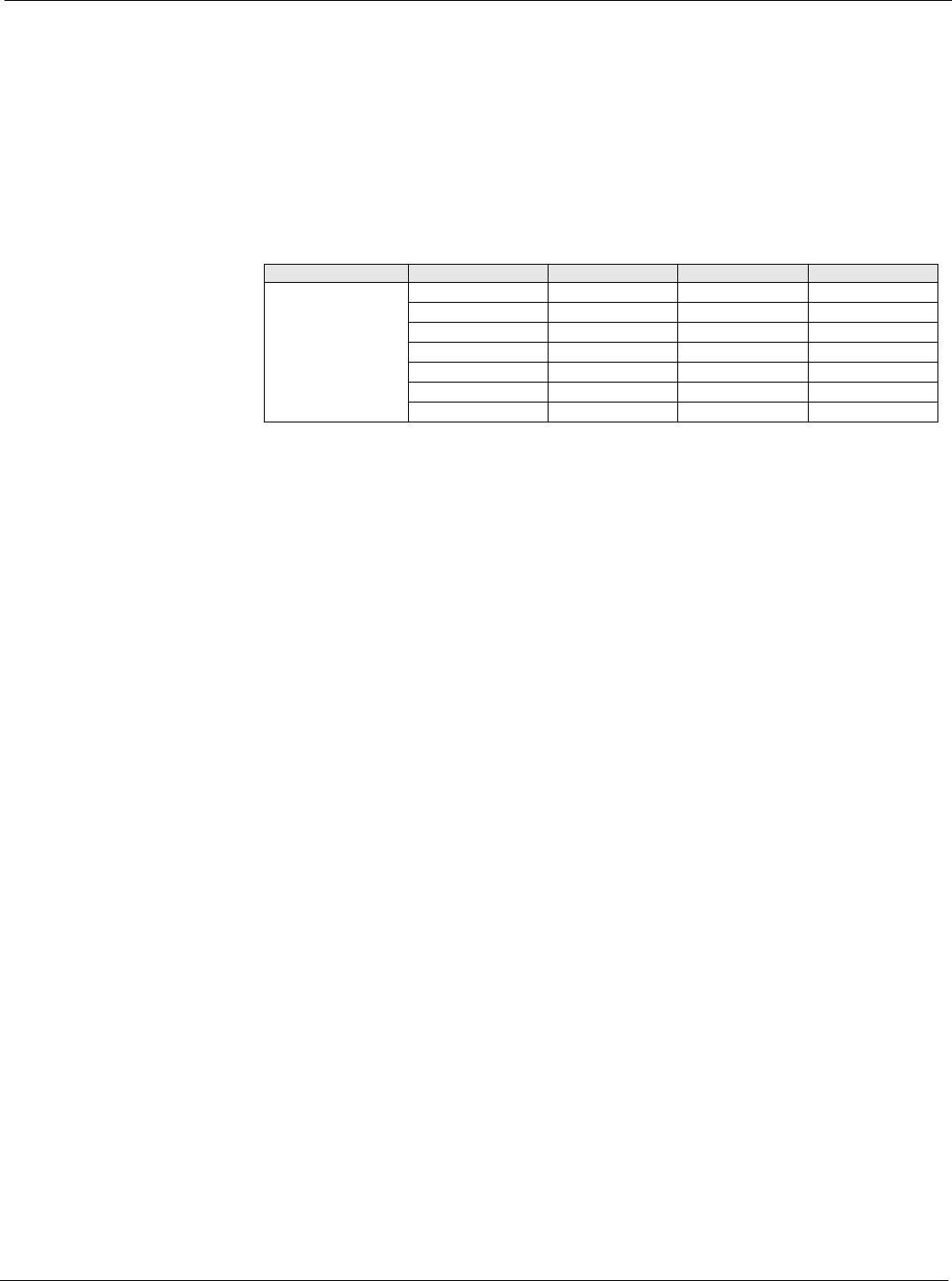
Table 34: Design Flow Setup Menu
Menu Display Name Item Display Name Default Setting Range Password Level
Design Flow Setup Des Flo DB= 3% 0-100% 4
DF Period= 30s 0-999s 4
Des Flo Gain= 0.1 0.0-100.0 4
DF Max Chg= 5% 0-100% 4
Design Flow= Yes Ye s/No 4
LH Lvl Pos= - 0.00-100.00% 4
RH Lvl Pos= - 0.00-100.00% 4