
Instruction manual


Table Of Contents
- Introduction
- Using the Keypad/Display
- Keypad/Display Menu Structure
- System Summary Menu
- Standard Menus
- System Menu
- Occupancy Menu
- Temperature Menu
- Flow Summary Menu
- Supply Fan Speed Menu
- Return/Exhaust Fan Speed Menu
- Cooling Menu
- Head Pressure Menu
- Evap Condensing Menu
- Economizer Menu
- Min OA Damper Menu
- Heating Menu
- Energy Recovery
- Dehumidification Menu
- Daily Schedule Menu
- One Event Schedule Menu
- Holiday Schedule Menu
- Optimal Start Menu
- Operating Hours Menu
- Extended Menus
- Unit Setup Menu
- Timer Settings Menu
- Time/Date Menu
- Supply Fan Setup Menu
- Return/Exhaust Fan Setup Menu
- Zone Temperature Setup Menu
- Compressor Setup Menu
- Head Pressure Setup Menu
- Chilled Water Setup Menu
- Economizer Setup Menu
- Design Flow Setup Menu
- Heating Setup Menu
- Dehumidification Setup Menu
- Alarm Out Configuration Setup Menu
- Alarm Limits Setup Menu
- Manual Control Menu
- LON/BACnetIP/BACnetMSTP Setup Menu
- Active Alarm Menu
- Alarm Log Menu
- Advanced Menus
- Unit Configuration Setup Menu
- Save/Restore Menu
- Alarm Delays Setup Menu
- Analog Input Status Menu
- Universal I/O Status Menu
- Digital Input Status Menu
- Digital Output Status Menu
- Adv Setup Settings Menu
- Adv Status Parameters Menu
- Alarms
- Operator’s Guide
- Determining Unit State
- Off Operating State
- Start Up Operating State
- Recirculating Operating State
- Heating
- Economizer
- Mechanical Cooling
- Determining Unit Status
- Determining Control Mode
- Determining Cooling Status
- Determining Heat Status
- Determining Economizer Status
- Determining Cooling Capacity
- Determining Heating Capacity
- Determining Supply Air Fan Capacity
- Determining RF/EF Capacity
- Determining Outside Air Damper Position
- Determining Emergency Mode
- Determining Application Mode
- Determining Occupancy Status
- Determining Occupancy Mode
- Determining Occupancy Source
- Unoccupied Operation
- Scheduling
- Temperature Control Configurations
- Heat/Cool Changeover
- Dehumidification
- Energy Recovery
- Outside Air Damper Control
- Outside Air Damper Control, Two Position
- Special Procedures for Units with WRV and More Than Two Circuits.
- Water Pump Control
- Cooling: Multistage
- Cooling: Modulating
- Heating Control
- Modulating
- Min DAT
- Indoor Air Fan - On/Off Control
36 McQuay OM 920
Keypad/Display Menu Structure
Compressor Setup Menu
Clg DB is an adjustable item which sets a dead band around the discharge cooling setpoint
parameter. For example, if the discharge cooling setpoint parameter is set to 55ºF and the Clg
Db parameter is set to 2ºF the dead band around the set point would be from 56.0ºF to 54.0ºF.
Lead Circuit is an adjustable item used to set which circuit will be the Lead Circuit.
Staging Type is an adjustable item used to set the type of compressor staging to be used. If
dehumidification is active, Alternate Staging is used regardless of the Staging Type setting.
Stage Time is an adjustable item used to set a minimum time period between compressor
stage changes.
CfanOut1 Spt is an adjustable item used to set the OAT temperature that the first “controlled”
condenser fan stage on each circuit is turned on. The first controlled condenser fan output is
turned on when any compressor is on and the OAT rises above the Condenser Stage 1 Set
Point. The first controlled condenser fan output is turned off when all compressors are off or
the OAT drops below the Condenser Stage 1 Set Point by more than the Condenser Fan
Differential (Default = 105°F).
CfanOut2 Spt is an adjustable item used to set the OAT temperature that the second
“controlled” condenser fan stage on each circuit is turned on. The second controlled condenser
fan output is turned on when any compressor is on and the OAT rises above the Condenser
Stage 2 Set Point. The second controlled condenser fan output is turned off when all
compressors are off or the OAT drops below the Condenser Stage 2 Set Point by more than the
Condenser Fan Differential (Default = 105°F).
CfanOut3 Spt is an adjustable item used to set the OAT temperature that the third
“controlled” condenser fan stage on each circuit is turned on. The third controlled condenser
fan output is turned on when any compressor is on and the OAT rises above the Condenser
Stage 3 Set Point. The third controlled condenser fan output is turned off when all
compressors are off or the OAT drops below the Condenser Stage 3 Set Point by more than the
Condenser Fan Differential (Default = 105°F)
Cond Fan Diff is an adjustable item used to set the Condenser Fan Differential (Default =
5°F).
OAT Clg Lock is an adjustable item which sets the low outdoor air temperature mechanical
cooling lockout point. Mechanical cooling operation is disabled when the outdoor air
temperature sensor input falls below this set point.
OATDiff is an adjustable item which sets a differential above the OAT Clg Lock parameter.
Mechanical cooling operation is re-enabled when the outdoor air temperature sensor input
rises above the OAT Clg Lock value by more than this differential.
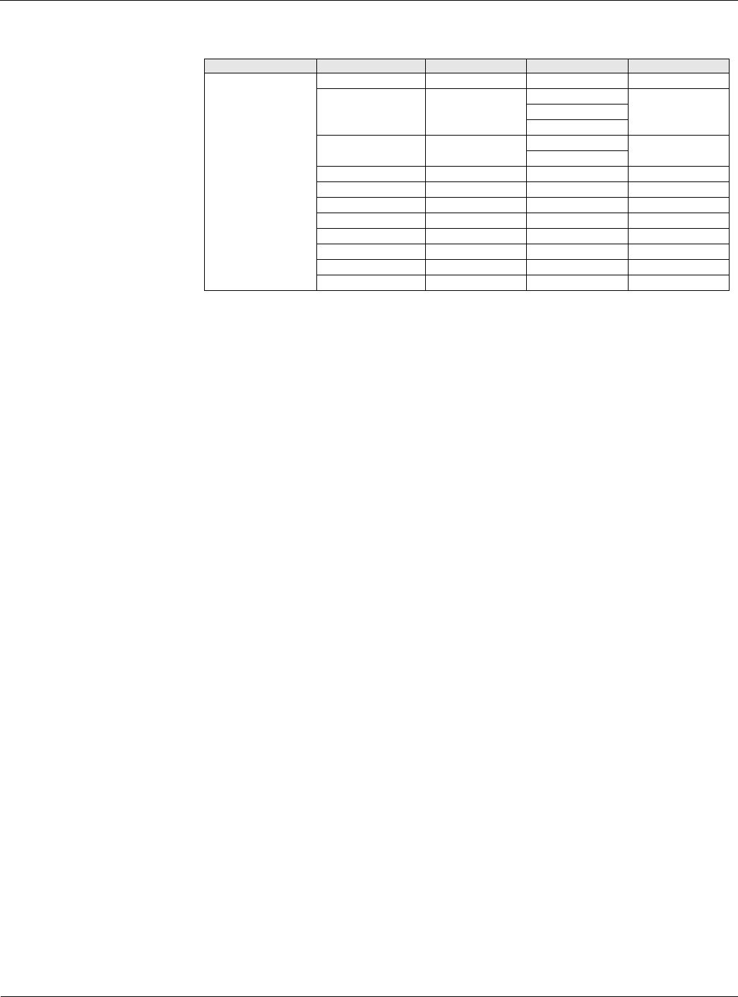
Table 30: Compressor Setup Menu
Menu Display Name Item Display Name Default Setting Range Password Level
Compressor Setup Clg DB= 2.0°F 1.0-10.0°F 4
Lead Circuit= #1 Auto 4
#1
#2
Staging Type= Standard Standard 4
Alternate
Stage Time= 5min 5-60min 4
CFanOut1 Spt= 105°F 0-105°F 4
CFanOut2 Spt= 105°F 0-105°F 4
CFanOut3 Spt= 105°F 0-105°F 4
Cond Fan Diff= 5°F 5-20°F 4
OAT Clg Lock= 55°F 0-100°F 4
OATDiff= 2d°F 0-10d°F 4
Min EWT= 55°F 20-100°F 4