
Instruction manual


Table Of Contents
- Introduction
- Using the Keypad/Display
- Keypad/Display Menu Structure
- System Summary Menu
- Standard Menus
- System Menu
- Occupancy Menu
- Temperature Menu
- Flow Summary Menu
- Supply Fan Speed Menu
- Return/Exhaust Fan Speed Menu
- Cooling Menu
- Head Pressure Menu
- Evap Condensing Menu
- Economizer Menu
- Min OA Damper Menu
- Heating Menu
- Energy Recovery
- Dehumidification Menu
- Daily Schedule Menu
- One Event Schedule Menu
- Holiday Schedule Menu
- Optimal Start Menu
- Operating Hours Menu
- Extended Menus
- Unit Setup Menu
- Timer Settings Menu
- Time/Date Menu
- Supply Fan Setup Menu
- Return/Exhaust Fan Setup Menu
- Zone Temperature Setup Menu
- Compressor Setup Menu
- Head Pressure Setup Menu
- Chilled Water Setup Menu
- Economizer Setup Menu
- Design Flow Setup Menu
- Heating Setup Menu
- Dehumidification Setup Menu
- Alarm Out Configuration Setup Menu
- Alarm Limits Setup Menu
- Manual Control Menu
- LON/BACnetIP/BACnetMSTP Setup Menu
- Active Alarm Menu
- Alarm Log Menu
- Advanced Menus
- Unit Configuration Setup Menu
- Save/Restore Menu
- Alarm Delays Setup Menu
- Analog Input Status Menu
- Universal I/O Status Menu
- Digital Input Status Menu
- Digital Output Status Menu
- Adv Setup Settings Menu
- Adv Status Parameters Menu
- Alarms
- Operator’s Guide
- Determining Unit State
- Off Operating State
- Start Up Operating State
- Recirculating Operating State
- Heating
- Economizer
- Mechanical Cooling
- Determining Unit Status
- Determining Control Mode
- Determining Cooling Status
- Determining Heat Status
- Determining Economizer Status
- Determining Cooling Capacity
- Determining Heating Capacity
- Determining Supply Air Fan Capacity
- Determining RF/EF Capacity
- Determining Outside Air Damper Position
- Determining Emergency Mode
- Determining Application Mode
- Determining Occupancy Status
- Determining Occupancy Mode
- Determining Occupancy Source
- Unoccupied Operation
- Scheduling
- Temperature Control Configurations
- Heat/Cool Changeover
- Dehumidification
- Energy Recovery
- Outside Air Damper Control
- Outside Air Damper Control, Two Position
- Special Procedures for Units with WRV and More Than Two Circuits.
- Water Pump Control
- Cooling: Multistage
- Cooling: Modulating
- Heating Control
- Modulating
- Min DAT
- Indoor Air Fan - On/Off Control
McQuay OM 920 35
Keypad/Display Menu Structure
Zone Temperature Setup Menu
Ctrl Temp Src is an adjustable item which selects the temperature sensor input to be used for
the unit heating/cooling changeover or zone cooling and heating capacity change decisions.
For example, if the CtrlTemp Src parameter is set to “Return,” then the Control Temp
parameter reads the same value as the Return Air parameter.
Use Tstat Spt is an adjustable item used to set whether to use the Tstat setpoint adjustment
value for the Zone Clg Spt and Zone Htg Spt.
Zone Clg DB is an adjustable item which sets a dead band around the Zone Cooling Setpoint
parameter. For example, if the Zone Cooling Setpoint parameter is set to 75ºF and the Clg
Deadband parameter is set to 2ºF the dead band around the set point would be from 76.0ºF to
74.0ºF.
Clg Period is an adjustable item which sets the “sampling time” used in the PI control
function to vary the DAT Clg Spt in zone control applications.
Clg Gain is an adjustable item which sets the “proportional band” used in the PI control
function to vary the DAT Clg Spt in zone control applications.
.Clg PAT is an adjustable item which sets the “project ahead” used in the PI control function
to vary the DAT Clg Spt in zone control applications.
Max Clg Change is an adjustable item that sets the maximum value for an increase or
decrease of the DAT Clg Spt in zone control applications.
Zone Htg DB is an adjustable item which sets a dead band around the Zone Heating Setpoint
parameter. For example, if the Zone Heating Setpoint parameter is set to 70ºF and the Htg
Deadband parameter is set to 2ºF the dead band around the set point would be from 69.0ºF to
71.0ºF.
Htg Period is an adjustable item which sets the “sampling time” used in the PI control
function to vary the DAT Htg Spt in zone control applications.
Htg Gain is an adjustable item which sets the “proportional band” used in the PI control
function to vary the DAT Htg Spt in zone control applications.
Htg PAT is an adjustable item which sets the “project ahead” used in the PI control function to
vary the DAT Htg Spt in zone control applications.
Max Htg Chg is an adjustable item that sets the maximum value for an increase or decrease of
the DAT Htg Spt in zone control applications.
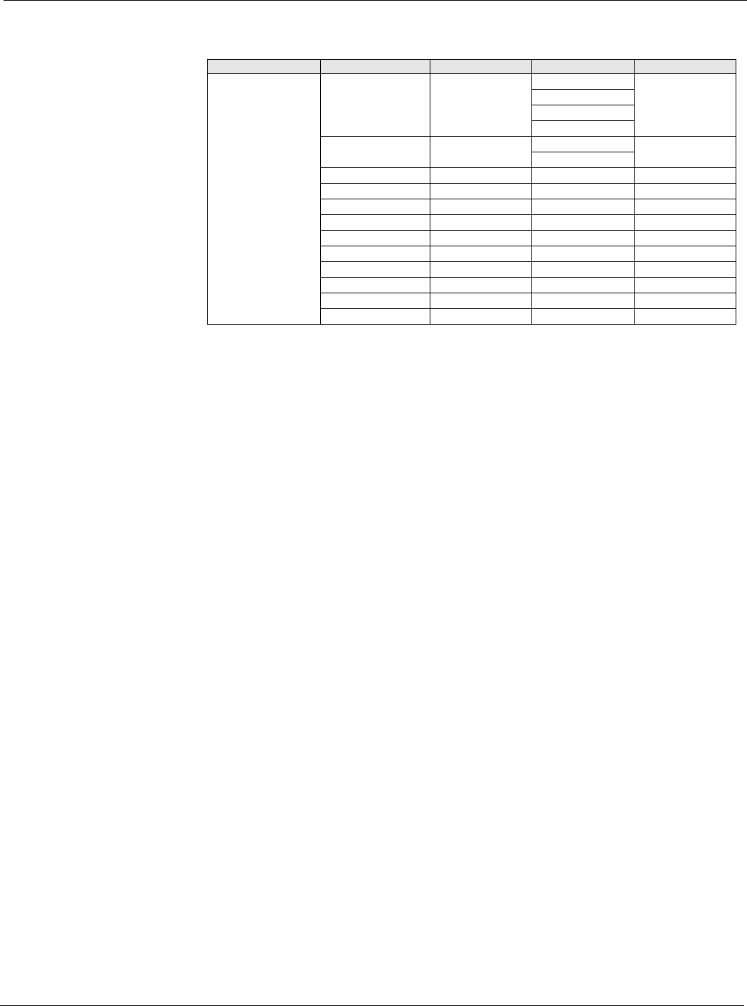
Table 29: Zone Temperature Setup Menu
Menu Display Name Item Display Name Default Setting Range Password Level
Zone Temp Setup Ctrl Temp Src= RAT RAT 4
Space
MAT
OAT
Use Tstat Spt= No No 4
Yes
Zone Clg DB= 2.0d°F 0.0-10.0d°F 4
Clg Period= 60s 0-999s 4
Clg Gain= 0.1 0.0-100.0 4
Clg PAT= 600s 0-999s 4
Max Clg Chg= 5.0d°F 0.0-50.0d°F 4
Zone Htg DB= 2.0d°F 0.0-10.0d°F 4
Htg Period= 60s 0-999s 4
Htg Gain= 0.1 0.0-100.0 4
Htg PAT= 600s 0-999s 4
Max Htg Chg= 5.0d°F 0.0-50.0d°F 4