
Instruction manual


Table Of Contents
- Introduction
- Using the Keypad/Display
- Keypad/Display Menu Structure
- System Summary Menu
- Standard Menus
- System Menu
- Occupancy Menu
- Temperature Menu
- Flow Summary Menu
- Supply Fan Speed Menu
- Return/Exhaust Fan Speed Menu
- Cooling Menu
- Head Pressure Menu
- Evap Condensing Menu
- Economizer Menu
- Min OA Damper Menu
- Heating Menu
- Energy Recovery
- Dehumidification Menu
- Daily Schedule Menu
- One Event Schedule Menu
- Holiday Schedule Menu
- Optimal Start Menu
- Operating Hours Menu
- Extended Menus
- Unit Setup Menu
- Timer Settings Menu
- Time/Date Menu
- Supply Fan Setup Menu
- Return/Exhaust Fan Setup Menu
- Zone Temperature Setup Menu
- Compressor Setup Menu
- Head Pressure Setup Menu
- Chilled Water Setup Menu
- Economizer Setup Menu
- Design Flow Setup Menu
- Heating Setup Menu
- Dehumidification Setup Menu
- Alarm Out Configuration Setup Menu
- Alarm Limits Setup Menu
- Manual Control Menu
- LON/BACnetIP/BACnetMSTP Setup Menu
- Active Alarm Menu
- Alarm Log Menu
- Advanced Menus
- Unit Configuration Setup Menu
- Save/Restore Menu
- Alarm Delays Setup Menu
- Analog Input Status Menu
- Universal I/O Status Menu
- Digital Input Status Menu
- Digital Output Status Menu
- Adv Setup Settings Menu
- Adv Status Parameters Menu
- Alarms
- Operator’s Guide
- Determining Unit State
- Off Operating State
- Start Up Operating State
- Recirculating Operating State
- Heating
- Economizer
- Mechanical Cooling
- Determining Unit Status
- Determining Control Mode
- Determining Cooling Status
- Determining Heat Status
- Determining Economizer Status
- Determining Cooling Capacity
- Determining Heating Capacity
- Determining Supply Air Fan Capacity
- Determining RF/EF Capacity
- Determining Outside Air Damper Position
- Determining Emergency Mode
- Determining Application Mode
- Determining Occupancy Status
- Determining Occupancy Mode
- Determining Occupancy Source
- Unoccupied Operation
- Scheduling
- Temperature Control Configurations
- Heat/Cool Changeover
- Dehumidification
- Energy Recovery
- Outside Air Damper Control
- Outside Air Damper Control, Two Position
- Special Procedures for Units with WRV and More Than Two Circuits.
- Water Pump Control
- Cooling: Multistage
- Cooling: Modulating
- Heating Control
- Modulating
- Min DAT
- Indoor Air Fan - On/Off Control
34 McQuay OM 920
Keypad/Display Menu Structure
Return/Exhaust Fan Setup Menu
BSP Ctrl Delay is an adjustable item that sets the duration of time that the minimum speed
signal is sent to the VFD after the return fan is started via a digital output. Control reverts to
either building pressure or speed after the fan has been on for the BSPCtrlDelay (default 30
seconds).
BSP DB is an adjustable item which sets a dead band around the BldgSP Spt parameter. No
building static pressure control action is taken when the current building static pressure input
is within this dead band.
BSP Period is an adjustable item which sets the “sampling period” used in the PI control
function that modulates the return air or exhaust fan VFD.
BSP Gain is an adjustable item which sets the “gain” used in the PI control function that
modulates the return air or exhaust fan VFD.
Max Spd Chg is an adjustable item that sets the maximum value for a VFD speed increase or
decrease. This speed change (either a positive or negative value) is added to the current fan
speed whenever the building static pressure is outside of the deadband, and a counter exceeds
the sample time.
Sup Fan Max is an adjustable item used with the RF@SF Max parameter described below to
set the SAF/RAF tracking offset at the high end.
RF@SF Max is an adjustable item that sets the speed of the return/exhaust fan when the
supply fan is at the Sup Fan Max value.
Sup Fan Min is an adjustable item used with the RF@SF Min parameter described below to
set the SAF/RAF tracking offset at the low end.
RF@SF Min is an adjustable item that sets the maximum speed of the return/exhaust fan
when the supply fan is at its minimum speed.
Min Speed is an adjustable item the sets the minimum speed of the RF/EF fan.
MinExStrtTime is an adjustable item that sets the Minimum Exhaust Fan On Time (Default =
120 seconds).
MinExStopTime is an adjustable item that sets the Minimum Exhaust Fan Stop Time (Default
= 120 seconds).
MinExhOAPos is an adjustable item that sets the Minimum Exhaust OA Position (default
5%). %). The outdoor air dampers must be open more that this value for prop exhaust fan
operation.
MinExhSAFCap is an adjustable item that sets the Minimum Exhaust SAF capacity (default
10%). The supply air fan speed must be higher than this value for prop exhaust fan operation.
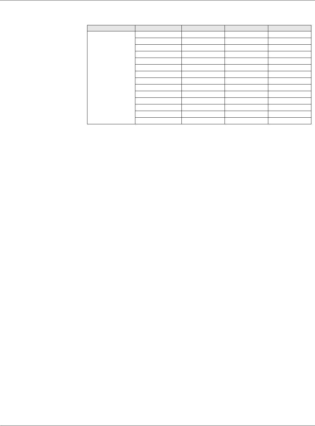
Table 28: Return/Exhaust Fan Setup Menu
Menu Display Name Item Display Name Default Setting Range Password Level
Ret/Exh Fan Setup BSP Ctrl Dly= 30s 0-999s 4
BSP DB= 0.01in 0.0-0.1in 4
BSP Period= 5s 0-999s 4
BSP Gain= 0.2 0.0-100.0s 4
Max Spd Chg= 4% 0-100% 4
Sup Fan Max= 100% 0-100% 4
RF @ SF Max 95% 0-100% 4
Sup Fan Min= 30% 0-100% 4
RF @ SF Min= 25% 0-100% 4
Min Speed= 5% 0-100% 4
MinExStrtTime= 120s 60-300s 4
MinExStopTime= 120s 60-300s 4
MinExhOAPos= 5% 0-100% 4
MinExhSAFCap= 10% 0-100% 4