
Instruction manual


Table Of Contents
- Introduction
- Using the Keypad/Display
- Keypad/Display Menu Structure
- System Summary Menu
- Standard Menus
- System Menu
- Occupancy Menu
- Temperature Menu
- Flow Summary Menu
- Supply Fan Speed Menu
- Return/Exhaust Fan Speed Menu
- Cooling Menu
- Head Pressure Menu
- Evap Condensing Menu
- Economizer Menu
- Min OA Damper Menu
- Heating Menu
- Energy Recovery
- Dehumidification Menu
- Daily Schedule Menu
- One Event Schedule Menu
- Holiday Schedule Menu
- Optimal Start Menu
- Operating Hours Menu
- Extended Menus
- Unit Setup Menu
- Timer Settings Menu
- Time/Date Menu
- Supply Fan Setup Menu
- Return/Exhaust Fan Setup Menu
- Zone Temperature Setup Menu
- Compressor Setup Menu
- Head Pressure Setup Menu
- Chilled Water Setup Menu
- Economizer Setup Menu
- Design Flow Setup Menu
- Heating Setup Menu
- Dehumidification Setup Menu
- Alarm Out Configuration Setup Menu
- Alarm Limits Setup Menu
- Manual Control Menu
- LON/BACnetIP/BACnetMSTP Setup Menu
- Active Alarm Menu
- Alarm Log Menu
- Advanced Menus
- Unit Configuration Setup Menu
- Save/Restore Menu
- Alarm Delays Setup Menu
- Analog Input Status Menu
- Universal I/O Status Menu
- Digital Input Status Menu
- Digital Output Status Menu
- Adv Setup Settings Menu
- Adv Status Parameters Menu
- Alarms
- Operator’s Guide
- Determining Unit State
- Off Operating State
- Start Up Operating State
- Recirculating Operating State
- Heating
- Economizer
- Mechanical Cooling
- Determining Unit Status
- Determining Control Mode
- Determining Cooling Status
- Determining Heat Status
- Determining Economizer Status
- Determining Cooling Capacity
- Determining Heating Capacity
- Determining Supply Air Fan Capacity
- Determining RF/EF Capacity
- Determining Outside Air Damper Position
- Determining Emergency Mode
- Determining Application Mode
- Determining Occupancy Status
- Determining Occupancy Mode
- Determining Occupancy Source
- Unoccupied Operation
- Scheduling
- Temperature Control Configurations
- Heat/Cool Changeover
- Dehumidification
- Energy Recovery
- Outside Air Damper Control
- Outside Air Damper Control, Two Position
- Special Procedures for Units with WRV and More Than Two Circuits.
- Water Pump Control
- Cooling: Multistage
- Cooling: Modulating
- Heating Control
- Modulating
- Min DAT
- Indoor Air Fan - On/Off Control
McQuay OM 920 33
Keypad/Display Menu Structure
Time/Date Menu
Time = is an adjustable item that sets the current time.
Date= is an adjustable item that sets the current date.
Supply Fan Setup Menu
DSP Ctrl Dly is an adjustable item that sets the duration of time that the minimum speed
signal is sent to the VFD after the supply fan is started via a digital output. Control reverts to
either duct pressure or speed after the fan has been on for the DSPCtrlDelay (default 30
seconds).
Min Speed is an adjustable item which is used to set the minimum supply fan speed (default
25%).
DSP DB is an adjustable item which sets a dead band around the DuctSP Spt parameter. No
duct static pressure control action is taken when the current duct static pressure input is within
this dead band.
VFD Ramp Time is an adjustable item that sets the amount of time it will take for the VFD to
drive from its minimum to maximum settings as well as its maximum to minimum settings.
The VFD Ramp Time value on the keypad must be changed whenever the Ramp Time of the
VFD is changed. The Ramp up Time must equal the Ramp down Time to provide stable
operation.
Min Period is an adjustable item that sets the duration of the sample time between VFD speed
changes. A counter is reset to zero whenever a speed change is added to the speed or duct
static pressure control is not active.
Note – The sample time must be long enough to allow the static pressure to get very close to its
steady state value before another calculation is made.
Max Spd Chg is an adjustable item that sets the maximum value for a VFD speed increase or
decrease. This speed change (either a positive or negative value) is added to the current fan
speed whenever the duct static pressure is outside of the deadband, and a counter exceeds the
sample time.
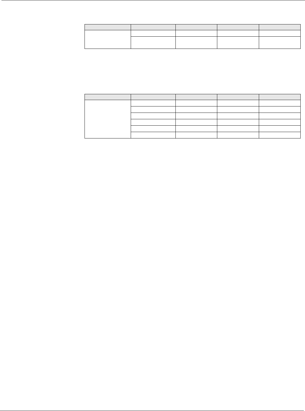
Table 26: Time/Date Menu
Menu Display Name Item Display Name Default Setting Range Password Level
Time/Date Time= HH:MM:SS 4
Date= MM/DD/YYYY 4
Table 27: Supply Fan Setup Menu
Menu Display Name Item Display Name Default Setting Range Password Level
Supply Fan Setup DSP Ctrl Dly= 30s 0-999s 4
Min Speed = 25% 0-100% 4
DSP DB= 0.1in 0-0.5in 4
VFD Ramp Time= 60s 0-999s 4
Min Period= 5s 0-999s 4
Max Spd Chg= 15% 0-100% 4