
Instruction manual


Table Of Contents
- Introduction
- Using the Keypad/Display
- Keypad/Display Menu Structure
- System Summary Menu
- Standard Menus
- System Menu
- Occupancy Menu
- Temperature Menu
- Flow Summary Menu
- Supply Fan Speed Menu
- Return/Exhaust Fan Speed Menu
- Cooling Menu
- Head Pressure Menu
- Evap Condensing Menu
- Economizer Menu
- Min OA Damper Menu
- Heating Menu
- Energy Recovery
- Dehumidification Menu
- Daily Schedule Menu
- One Event Schedule Menu
- Holiday Schedule Menu
- Optimal Start Menu
- Operating Hours Menu
- Extended Menus
- Unit Setup Menu
- Timer Settings Menu
- Time/Date Menu
- Supply Fan Setup Menu
- Return/Exhaust Fan Setup Menu
- Zone Temperature Setup Menu
- Compressor Setup Menu
- Head Pressure Setup Menu
- Chilled Water Setup Menu
- Economizer Setup Menu
- Design Flow Setup Menu
- Heating Setup Menu
- Dehumidification Setup Menu
- Alarm Out Configuration Setup Menu
- Alarm Limits Setup Menu
- Manual Control Menu
- LON/BACnetIP/BACnetMSTP Setup Menu
- Active Alarm Menu
- Alarm Log Menu
- Advanced Menus
- Unit Configuration Setup Menu
- Save/Restore Menu
- Alarm Delays Setup Menu
- Analog Input Status Menu
- Universal I/O Status Menu
- Digital Input Status Menu
- Digital Output Status Menu
- Adv Setup Settings Menu
- Adv Status Parameters Menu
- Alarms
- Operator’s Guide
- Determining Unit State
- Off Operating State
- Start Up Operating State
- Recirculating Operating State
- Heating
- Economizer
- Mechanical Cooling
- Determining Unit Status
- Determining Control Mode
- Determining Cooling Status
- Determining Heat Status
- Determining Economizer Status
- Determining Cooling Capacity
- Determining Heating Capacity
- Determining Supply Air Fan Capacity
- Determining RF/EF Capacity
- Determining Outside Air Damper Position
- Determining Emergency Mode
- Determining Application Mode
- Determining Occupancy Status
- Determining Occupancy Mode
- Determining Occupancy Source
- Unoccupied Operation
- Scheduling
- Temperature Control Configurations
- Heat/Cool Changeover
- Dehumidification
- Energy Recovery
- Outside Air Damper Control
- Outside Air Damper Control, Two Position
- Special Procedures for Units with WRV and More Than Two Circuits.
- Water Pump Control
- Cooling: Multistage
- Cooling: Modulating
- Heating Control
- Modulating
- Min DAT
- Indoor Air Fan - On/Off Control
32 McQuay OM 920
Keypad/Display Menu Structure
Timer Settings Menu
Service Time is an adjustable item that sets the amount of time the internal control timers can
be temporarily sped up.
Startup is an adjustable item that sets the time in seconds that the unit will perform its startup
operation.
Recirculate is an adjustable item that sets the time in seconds that the unit operates with only
the fan, recirculating the building air upon unit start up.
Zero OA Time is an adjustable item that sets the time in minutes that the outdoor air damper
stays at a zero position upon unit start up.
Tnt Override is an adjustable item that sets the amount of time that the unit will go into
operation when the tenant override function is activated. Tenant override can be activated by
the space sensor button, the network occupancy mode parameter or the keypad Occ Mode=
parameter.
Post Heat is an adjustable item that sets the duration of the post heat function available on
VAV u n i t s .
Password is an adjustable item that sets the amount of time in minutes that the controller will
allow access to applicable menus without re-entering the necessary password. If the keypad
display remains idle for this time period, the display will revert to the “main menu” requiring a
re-enter of the password.
Low DAT is an adjustable item that sets the duration of a time period upon unit start up during
which the Low Discharge Temperature fault is ignored. This may be particularly important in
colder climates when a unit has been off for a significant time period during which the unit,
including the discharge air temperature sensor, has become very cold. This time period allows
the unit to run long enough to turn the unit heat on and warm the discharge sensor above the
alarm limit, preventing nuisance unit alarm shutdown. This time period begins when the
supply fan starts.
ClgStateDelay is an adjustable item that sets the amount of time between the fan only
operating state and the mechanical cooling state. The unit will not enter the mechanical
cooling state until this time has passed. This only applies on discharge control units following
morning warm up heating operation.
Bypass Valve is an adjustable item that sets the duration of time the bypass valve is to be
opened prior to entering the economizer (waterside) or cooling operating state on unit with a
water cooled condenser. This is to allow enough time for the water flow switch and the
entering water temperature to be checked before the unit begins economizer or cooling
operation.
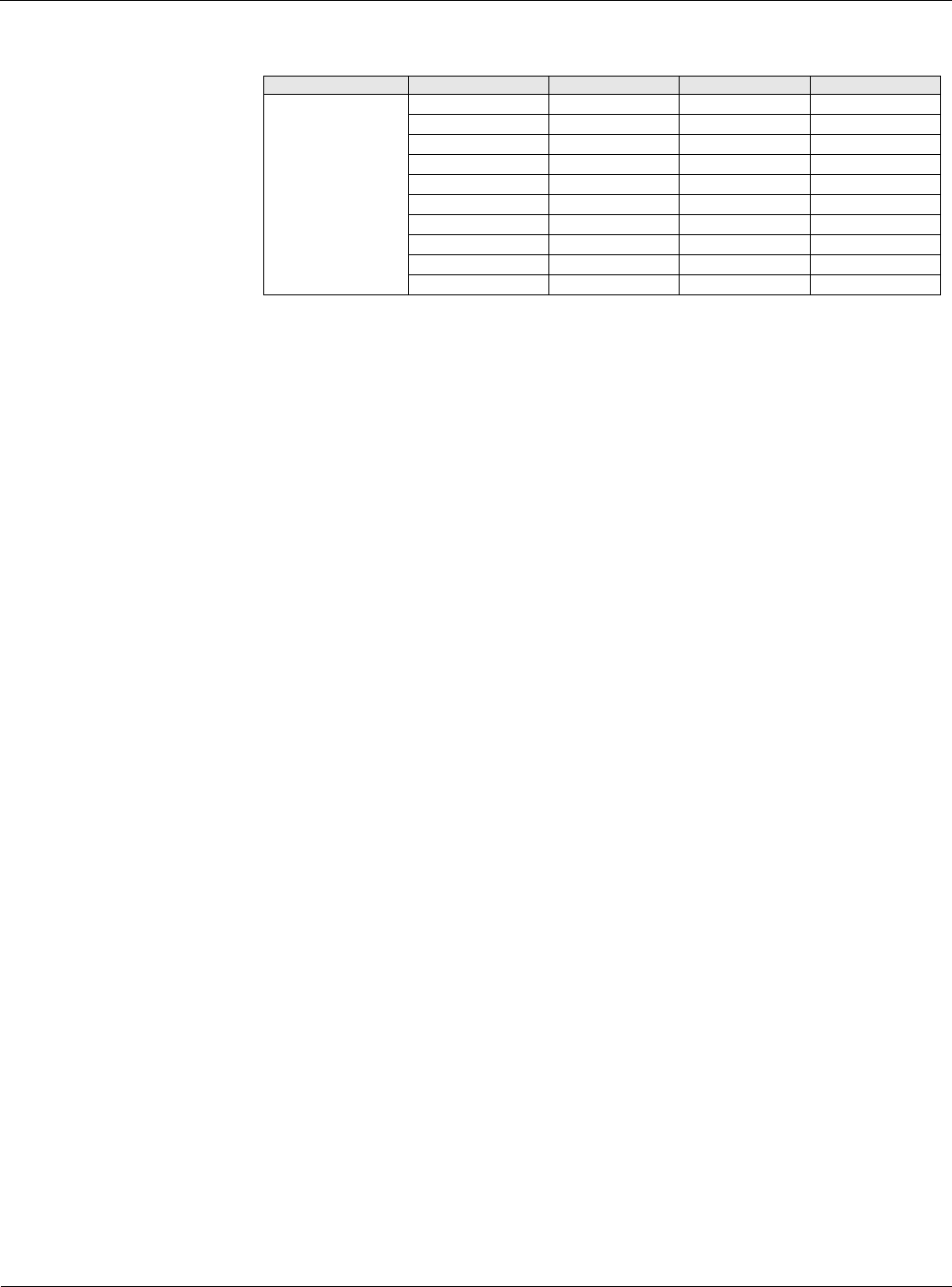
Table 25: Timer Settings Menu
Menu Display Name Item Display Name Default Setting Range Password Level
Timer Settings Service Time= 0min 0-240min 4
Start Up= 180s 1800s 4
Recirculate= 180s 3600s 4
Zero OA Time= 0min 0-240min 4
Tnt Override= 120min 0300min 4
Post Heat= 0s 0-180s 4
Password= 10min 3-30min 4
Low DAT= 6min 0-60min 4
ClgStateDelay= 300s 0-600s 4
Bypass Valve= 300s 0-600s 4