
Instruction manual


Table Of Contents
- Introduction
- Using the Keypad/Display
- Keypad/Display Menu Structure
- System Summary Menu
- Standard Menus
- System Menu
- Occupancy Menu
- Temperature Menu
- Flow Summary Menu
- Supply Fan Speed Menu
- Return/Exhaust Fan Speed Menu
- Cooling Menu
- Head Pressure Menu
- Evap Condensing Menu
- Economizer Menu
- Min OA Damper Menu
- Heating Menu
- Energy Recovery
- Dehumidification Menu
- Daily Schedule Menu
- One Event Schedule Menu
- Holiday Schedule Menu
- Optimal Start Menu
- Operating Hours Menu
- Extended Menus
- Unit Setup Menu
- Timer Settings Menu
- Time/Date Menu
- Supply Fan Setup Menu
- Return/Exhaust Fan Setup Menu
- Zone Temperature Setup Menu
- Compressor Setup Menu
- Head Pressure Setup Menu
- Chilled Water Setup Menu
- Economizer Setup Menu
- Design Flow Setup Menu
- Heating Setup Menu
- Dehumidification Setup Menu
- Alarm Out Configuration Setup Menu
- Alarm Limits Setup Menu
- Manual Control Menu
- LON/BACnetIP/BACnetMSTP Setup Menu
- Active Alarm Menu
- Alarm Log Menu
- Advanced Menus
- Unit Configuration Setup Menu
- Save/Restore Menu
- Alarm Delays Setup Menu
- Analog Input Status Menu
- Universal I/O Status Menu
- Digital Input Status Menu
- Digital Output Status Menu
- Adv Setup Settings Menu
- Adv Status Parameters Menu
- Alarms
- Operator’s Guide
- Determining Unit State
- Off Operating State
- Start Up Operating State
- Recirculating Operating State
- Heating
- Economizer
- Mechanical Cooling
- Determining Unit Status
- Determining Control Mode
- Determining Cooling Status
- Determining Heat Status
- Determining Economizer Status
- Determining Cooling Capacity
- Determining Heating Capacity
- Determining Supply Air Fan Capacity
- Determining RF/EF Capacity
- Determining Outside Air Damper Position
- Determining Emergency Mode
- Determining Application Mode
- Determining Occupancy Status
- Determining Occupancy Mode
- Determining Occupancy Source
- Unoccupied Operation
- Scheduling
- Temperature Control Configurations
- Heat/Cool Changeover
- Dehumidification
- Energy Recovery
- Outside Air Damper Control
- Outside Air Damper Control, Two Position
- Special Procedures for Units with WRV and More Than Two Circuits.
- Water Pump Control
- Cooling: Multistage
- Cooling: Modulating
- Heating Control
- Modulating
- Min DAT
- Indoor Air Fan - On/Off Control
28 McQuay OM 920
Keypad/Display Menu Structure
Dehumidification Menu
Dehum Status is a status only item that indicates whether dehumidification is enabled or
disabled.
Rel Humidity is a status only item that indicates the current relative humidity reading of the
sensor.
DewPoint is a status only item that indicates the current value that is calculated by the
controller using the Rel Humidity value and either the Space Temp or Return Air value,
depending on the setting of the Humidity Sensor Location. This parameter can either be set to
“Space” or “Return.”
Dehum Method is an adjustable item used to set the dehumidification method to either “RH”
or “DewPt.” When this parameter is set to “RH,” dehumidification operation is controlled to
maintain the Rel Humidity value at the Relative Humidity Set Point. When this parameter is
set to “DewPt,” dehumidification operation is controlled to maintain the Dew Point= value at
the Dew Point Set Point.
RH Setpoint is an adjustable item used to set the relative humidity value at which the relative
humidity will be controlled to during dehumidification operation.
Dewpoint Spt is an adjustable item used to set the Dewpoint value at which the dewpoint with
will be controlled to during dehumidification operation.
Reheat Spt is a status only item which is used to indicate the DAT temperature to which the
HGRH valve will be controlled to in the Cooling and Fan Only operating states while
dehumidification operation is active. The Reheat Setpoint equals the DAT Cooling Setpoint
for DAT controlled units and will vary in between the minimum and maximum reheat setpoint
for Zone Controlled units.
Reheat Cap is a status only item that indicates the current reheat capacity value.
Daily Schedule Menu
The Daily Schedule sets the start and stop times for each of the days of the week. One start and
one stop time can be set for each day.
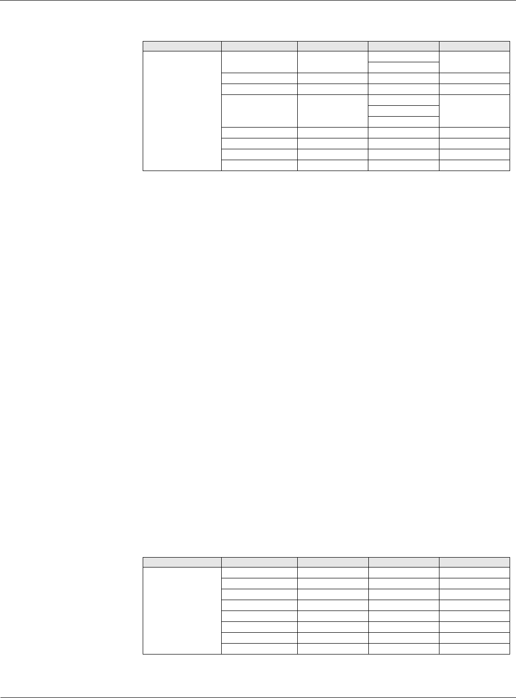
Table 17: Dehumidification Menu
Menu Display Name Item Display Name Default Setting Range Password Level
Dehumidification Dehum Status= - Disabled 6
Enabled
Rel Humidity= - 0-100% 6
Dewpoint= - -50-150°F 6
Dehum Method= None None 6
Rel Hum
DewPt
RH Setpoint= 50% 0-100% 6
Dewpoint Spt= 50°F 0-100°F 6
Reheat Spt= - 40.0-100.0°F 6
Reheat Cap = - 0-100% 6
Table 18: Daily Schedule Menu
Menu Display Name Item Display Name Default Setting Range Password Level
Daily Schedule Mon= 00:00 – 00:00 00:00 – 23:59 6
Tue= 00:00 – 00:00 00:00 – 23:59 6
Wed= 00:00 – 00:00 00:00 – 23:59 6
Thu= 00:00 – 00:00 00:00 – 23:59 6
Fri= 00:00 – 00:00 00:00 – 23:59 6
Sat= 00:00 – 00:00 00:00 – 23:59 6
Sun= 00:00 – 00:00 00:00 – 23:59 6
Hol= 00:00 – 00:00 00:00 – 23:59 6