
Instruction manual


Table Of Contents
- Introduction
- Using the Keypad/Display
- Keypad/Display Menu Structure
- System Summary Menu
- Standard Menus
- System Menu
- Occupancy Menu
- Temperature Menu
- Flow Summary Menu
- Supply Fan Speed Menu
- Return/Exhaust Fan Speed Menu
- Cooling Menu
- Head Pressure Menu
- Evap Condensing Menu
- Economizer Menu
- Min OA Damper Menu
- Heating Menu
- Energy Recovery
- Dehumidification Menu
- Daily Schedule Menu
- One Event Schedule Menu
- Holiday Schedule Menu
- Optimal Start Menu
- Operating Hours Menu
- Extended Menus
- Unit Setup Menu
- Timer Settings Menu
- Time/Date Menu
- Supply Fan Setup Menu
- Return/Exhaust Fan Setup Menu
- Zone Temperature Setup Menu
- Compressor Setup Menu
- Head Pressure Setup Menu
- Chilled Water Setup Menu
- Economizer Setup Menu
- Design Flow Setup Menu
- Heating Setup Menu
- Dehumidification Setup Menu
- Alarm Out Configuration Setup Menu
- Alarm Limits Setup Menu
- Manual Control Menu
- LON/BACnetIP/BACnetMSTP Setup Menu
- Active Alarm Menu
- Alarm Log Menu
- Advanced Menus
- Unit Configuration Setup Menu
- Save/Restore Menu
- Alarm Delays Setup Menu
- Analog Input Status Menu
- Universal I/O Status Menu
- Digital Input Status Menu
- Digital Output Status Menu
- Adv Setup Settings Menu
- Adv Status Parameters Menu
- Alarms
- Operator’s Guide
- Determining Unit State
- Off Operating State
- Start Up Operating State
- Recirculating Operating State
- Heating
- Economizer
- Mechanical Cooling
- Determining Unit Status
- Determining Control Mode
- Determining Cooling Status
- Determining Heat Status
- Determining Economizer Status
- Determining Cooling Capacity
- Determining Heating Capacity
- Determining Supply Air Fan Capacity
- Determining RF/EF Capacity
- Determining Outside Air Damper Position
- Determining Emergency Mode
- Determining Application Mode
- Determining Occupancy Status
- Determining Occupancy Mode
- Determining Occupancy Source
- Unoccupied Operation
- Scheduling
- Temperature Control Configurations
- Heat/Cool Changeover
- Dehumidification
- Energy Recovery
- Outside Air Damper Control
- Outside Air Damper Control, Two Position
- Special Procedures for Units with WRV and More Than Two Circuits.
- Water Pump Control
- Cooling: Multistage
- Cooling: Modulating
- Heating Control
- Modulating
- Min DAT
- Indoor Air Fan - On/Off Control
24 McQuay OM 920
Keypad/Display Menu Structure
Min OA Damper Menu
Min OA Pos is a status only item which indicates the current minimum position of the
outdoor damper. This value does not go above a value called the Ventilation Limit and does
not go below a value called the Demand Control Ventilation Limit.
On CAV units the Ventilation Limit and the Demand Control Ventilation Limit are fixed
values set equal to the Vent Limit= and DCV Limit= parameters. On VAV units the OA
Damper Position increases from the Vent Limit= value to the LoFloVent Limit= value as the
VFD speed goes from 100% down to the Min Clg Spd= value. The Demand Control
Ventilation Limit in this VAV case is determined by the Ventilation Limit X DVC Limit=/Vent
Limit=. When the Min OA Reset= parameter is set to “None” the Min OA Pos= value is set to
the Ventilation Limit. If Min OA Reset= is set to Network, Ext VDC, Ext mA, IAQ VDC, or
IAQ mA, the Min OA Pos= varies between the Ventilation Limit and the Demand Control
Ventilation Limit as the reset signal varies from its maximum to minimum value.
Vent Li mit is an adjustable item that sets the value of the Ventilation Limit on a CAV unit or
when a VAV unit is at 100% discharge fan speed.
DCV Limit is an adjustable item that sets the value of the Demand Control Ventilation Limit
on a CAV unit or when a VAV unit is at 100% discharge fan speed. This item is only used
when the “Min OA Reset=” is set to something other than “None.”
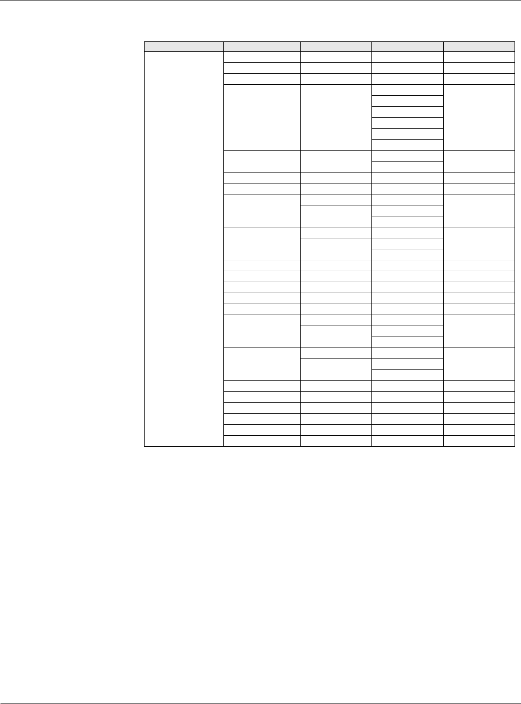
Table 14: Min OA Damper Menu
Menu Display Name Item Display Name Default Setting Range Password Level
Min OA Damper
Min OA Pos= - 0-100% 6
Vent Limit= 20% 0-100% 6
DCV Limit= 10% 0-100% 6
Min OA Reset= None None 6
Network
Ext VDC
Ext mA
IAQ VDC
IAQ mA
DesignFlow= Yes No 6
Yes
OA @ MinV/mA= 0% 0-100% 6
OA @ MaxV/mA= 100% 0-100% 6
Min V/mA= 0.0/ 0.0-20.0/ 6
V V
mA
Max V/mA= 10.0/ 0.0-20.0/ 6
V V
mA
PPM @DCV Lmt= 800ppm 0-5000ppm 6
PPM @Vnt Lmt= 1000ppm 0-5000ppm 6
PPM= - 0-5000ppm 6
Min PPM= 0ppm 0-5000ppm 6
Max PPM= 2000ppm 0-5000ppm 6
V/A @Min PPM= 0.0/ 0.0-20.0/ 6
V V
mA
V/A @Max PPM= 10.0/ 0.0-20.0/ 6
V V
mA
Min Fan Diff= 20% 0-100% 6
Max Fan Diff= 50% 0-100% 6
OA Flow= - 0-60000CFM 6
MinOAFlw Spt= 2000CFM 0-60000CFM 6
Min Clg Spd= 40% 0-100% 6
LoFlo V Lmt= 30% 0-100% 6