
Instruction manual


Table Of Contents
- Introduction
- Using the Keypad/Display
- Keypad/Display Menu Structure
- System Summary Menu
- Standard Menus
- System Menu
- Occupancy Menu
- Temperature Menu
- Flow Summary Menu
- Supply Fan Speed Menu
- Return/Exhaust Fan Speed Menu
- Cooling Menu
- Head Pressure Menu
- Evap Condensing Menu
- Economizer Menu
- Min OA Damper Menu
- Heating Menu
- Energy Recovery
- Dehumidification Menu
- Daily Schedule Menu
- One Event Schedule Menu
- Holiday Schedule Menu
- Optimal Start Menu
- Operating Hours Menu
- Extended Menus
- Unit Setup Menu
- Timer Settings Menu
- Time/Date Menu
- Supply Fan Setup Menu
- Return/Exhaust Fan Setup Menu
- Zone Temperature Setup Menu
- Compressor Setup Menu
- Head Pressure Setup Menu
- Chilled Water Setup Menu
- Economizer Setup Menu
- Design Flow Setup Menu
- Heating Setup Menu
- Dehumidification Setup Menu
- Alarm Out Configuration Setup Menu
- Alarm Limits Setup Menu
- Manual Control Menu
- LON/BACnetIP/BACnetMSTP Setup Menu
- Active Alarm Menu
- Alarm Log Menu
- Advanced Menus
- Unit Configuration Setup Menu
- Save/Restore Menu
- Alarm Delays Setup Menu
- Analog Input Status Menu
- Universal I/O Status Menu
- Digital Input Status Menu
- Digital Output Status Menu
- Adv Setup Settings Menu
- Adv Status Parameters Menu
- Alarms
- Operator’s Guide
- Determining Unit State
- Off Operating State
- Start Up Operating State
- Recirculating Operating State
- Heating
- Economizer
- Mechanical Cooling
- Determining Unit Status
- Determining Control Mode
- Determining Cooling Status
- Determining Heat Status
- Determining Economizer Status
- Determining Cooling Capacity
- Determining Heating Capacity
- Determining Supply Air Fan Capacity
- Determining RF/EF Capacity
- Determining Outside Air Damper Position
- Determining Emergency Mode
- Determining Application Mode
- Determining Occupancy Status
- Determining Occupancy Mode
- Determining Occupancy Source
- Unoccupied Operation
- Scheduling
- Temperature Control Configurations
- Heat/Cool Changeover
- Dehumidification
- Energy Recovery
- Outside Air Damper Control
- Outside Air Damper Control, Two Position
- Special Procedures for Units with WRV and More Than Two Circuits.
- Water Pump Control
- Cooling: Multistage
- Cooling: Modulating
- Heating Control
- Modulating
- Min DAT
- Indoor Air Fan - On/Off Control
McQuay OM 920 21
Keypad/Display Menu Structure
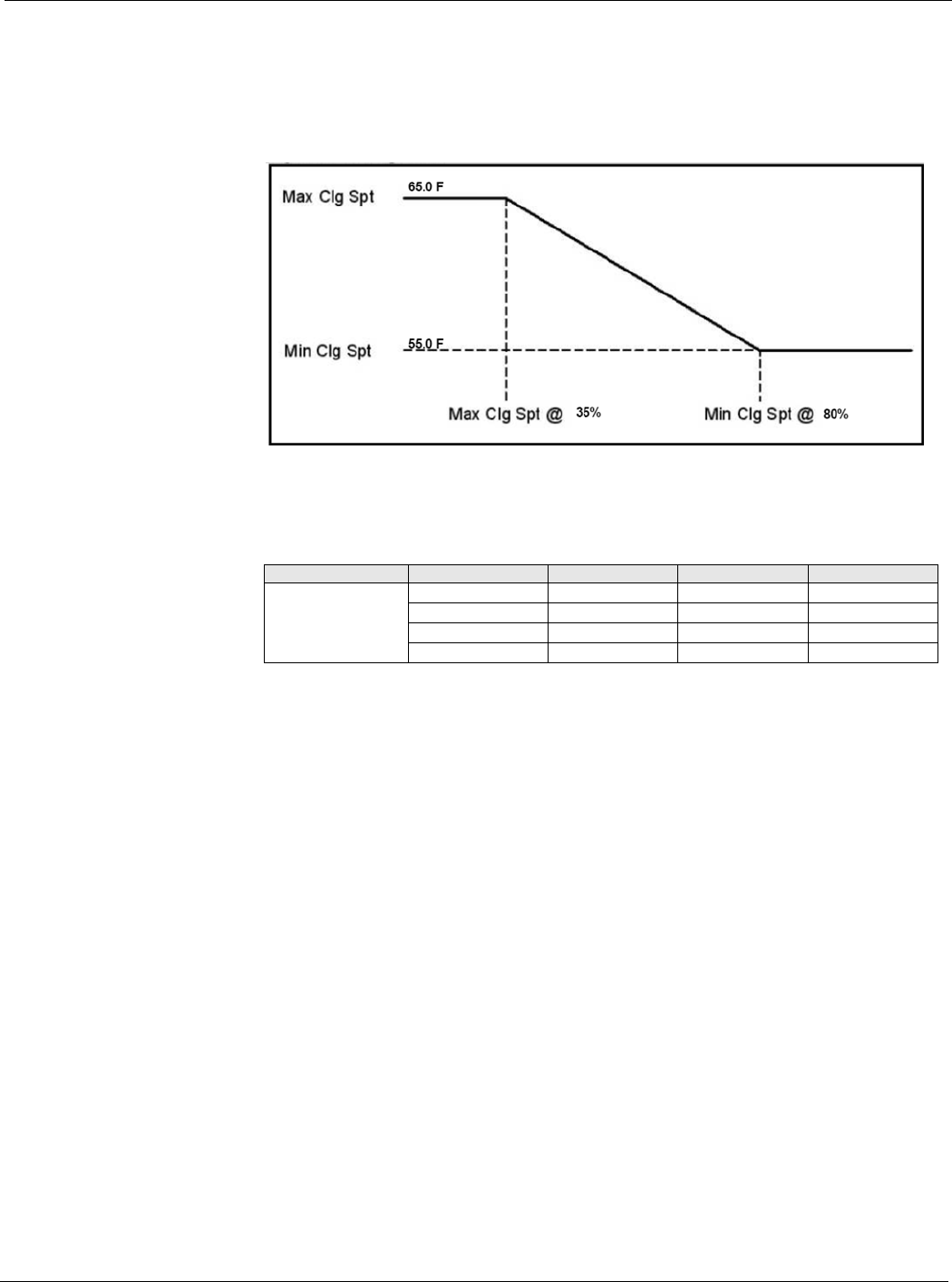
Max Clg Spt = 65.0 F
Max Clg Spt @ = 35%
Based on the above, the unit will have a discharge air temperature setpoint of 55.0 F from 80%
to 100% of the airflow.
Figure 5: Cooling Setpoint
Head Pressure Menu
The Head Pressure menu contains parameters that are used to maintain head pressure control.
WRV Pos is a status only item that indicates the current water regulating valve position.
Head P Circ 1 is a status only item that indicates the current refrigerant pressure for circuit
#1.
Head P Circ 2 is a status only item that indicates the current refrigerant pressure for circuit
#2.
Setpoint is an adjustable item that sets the refrigerant setpoint used for controlling the water
regulating valve. The water-regulating valve is modulated to maintain the refrigerant pressure.
Note – This section only applies to Self Contained units with a water regulating valve.
Table 11: Head Pressure Menu
Menu Display Name Item Display Name Default Setting Range Password Level
Head Pressure WRV Pos= - 0-100% 6
Head P Circ 1= - 0-750psi 6
Head P Circ 2= - 0-750psi 6
Setpoint= 260psi 230-340psi 6