
Instruction manual


Table Of Contents
- Introduction
- Using the Keypad/Display
- Keypad/Display Menu Structure
- System Summary Menu
- Standard Menus
- System Menu
- Occupancy Menu
- Temperature Menu
- Flow Summary Menu
- Supply Fan Speed Menu
- Return/Exhaust Fan Speed Menu
- Cooling Menu
- Head Pressure Menu
- Evap Condensing Menu
- Economizer Menu
- Min OA Damper Menu
- Heating Menu
- Energy Recovery
- Dehumidification Menu
- Daily Schedule Menu
- One Event Schedule Menu
- Holiday Schedule Menu
- Optimal Start Menu
- Operating Hours Menu
- Extended Menus
- Unit Setup Menu
- Timer Settings Menu
- Time/Date Menu
- Supply Fan Setup Menu
- Return/Exhaust Fan Setup Menu
- Zone Temperature Setup Menu
- Compressor Setup Menu
- Head Pressure Setup Menu
- Chilled Water Setup Menu
- Economizer Setup Menu
- Design Flow Setup Menu
- Heating Setup Menu
- Dehumidification Setup Menu
- Alarm Out Configuration Setup Menu
- Alarm Limits Setup Menu
- Manual Control Menu
- LON/BACnetIP/BACnetMSTP Setup Menu
- Active Alarm Menu
- Alarm Log Menu
- Advanced Menus
- Unit Configuration Setup Menu
- Save/Restore Menu
- Alarm Delays Setup Menu
- Analog Input Status Menu
- Universal I/O Status Menu
- Digital Input Status Menu
- Digital Output Status Menu
- Adv Setup Settings Menu
- Adv Status Parameters Menu
- Alarms
- Operator’s Guide
- Determining Unit State
- Off Operating State
- Start Up Operating State
- Recirculating Operating State
- Heating
- Economizer
- Mechanical Cooling
- Determining Unit Status
- Determining Control Mode
- Determining Cooling Status
- Determining Heat Status
- Determining Economizer Status
- Determining Cooling Capacity
- Determining Heating Capacity
- Determining Supply Air Fan Capacity
- Determining RF/EF Capacity
- Determining Outside Air Damper Position
- Determining Emergency Mode
- Determining Application Mode
- Determining Occupancy Status
- Determining Occupancy Mode
- Determining Occupancy Source
- Unoccupied Operation
- Scheduling
- Temperature Control Configurations
- Heat/Cool Changeover
- Dehumidification
- Energy Recovery
- Outside Air Damper Control
- Outside Air Damper Control, Two Position
- Special Procedures for Units with WRV and More Than Two Circuits.
- Water Pump Control
- Cooling: Multistage
- Cooling: Modulating
- Heating Control
- Modulating
- Min DAT
- Indoor Air Fan - On/Off Control
20 McQuay OM 920
Keypad/Display Menu Structure
Cooling Menu
Zone Clg Spt an adjustable item which sets the temperature in which the unit will go into the
cooling mode of operation.
Unocc Clg Spt is an adjustable item which sets the zone temperature at which the unit starts
up and provides unoccupied cooling (night setup) during unoccupied periods.
Note: Setting this to its minimum value will disable unoccupied cooling.
DAT Clg Spt is an adjustable item used by the controller to set the DAT cooling setpoint. This
value is adjustable only when it is not being set by a reset schedule.
Min Clg Spt is an adjustable item which sets the minimum cooling discharge set point for use
with a cooling discharge air temperature set point reset schedule.
Min Clg Spt @ is an adjustable item which sets the value of the sensor input, selected with
the Cooling Reset parameter, at which the DAT cooling setpoint parameter is reset to the
minimum DAT cooling setpoint value.
Clg Reset is an adjustable item used to set the type of cooling reset to be used.
Max Clg Spt is an adjustable item which sets the maximum cooling discharge set point for
use with a cooling discharge air temperature set point reset schedule.
Max Clg Spt @ is an adjustable item which sets the value of the sensor input, selected with
the Cooling Reset parameter, at which the DAT cooling setpoint parameter is reset to the
maximum DAT cooling setpoint value.
Figure 5 graphically shows the cooling reset operation. Example, The normal DAT cooling
setpoint is 55.0 F. The cooling reset scheme is set to airflow. The unit is to adjust the DAT
from 55.0 F to 65.0 F. When the unit is at 35% of the design airflow the discharge temperature
is to be 65.0 F. When the unit is at 80% of its airflow the DAT is to be 55.0F. This example
would give the following inputs:
Min Clg Spt = 55.0 F
Min Clg Spt @ = 80%
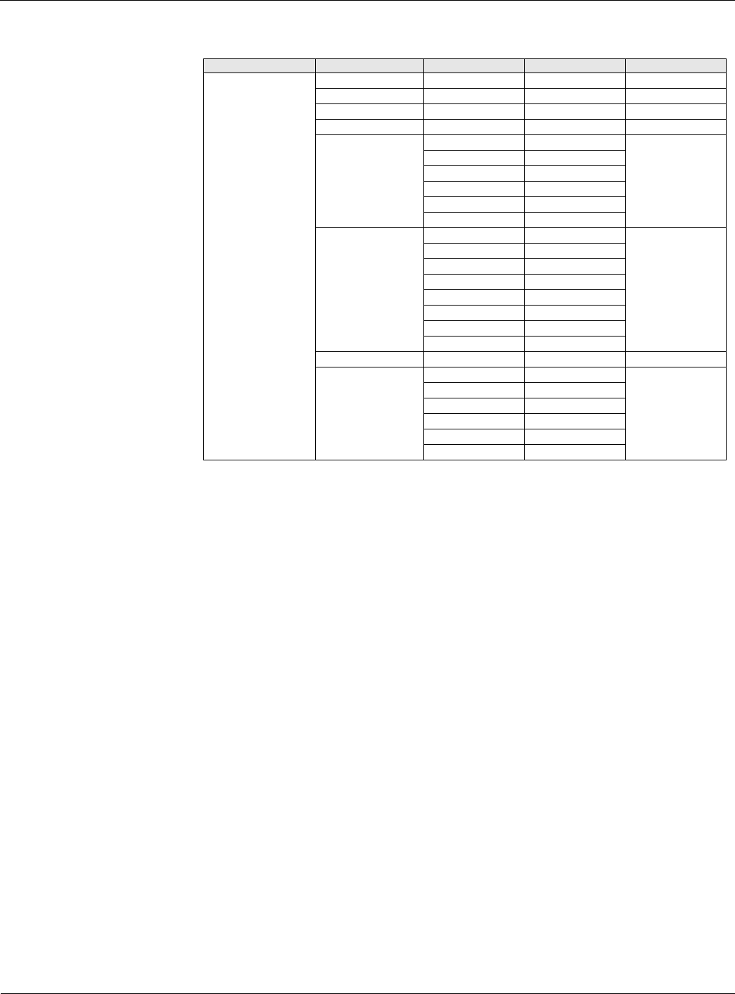
Table 10: Cooling Menu
Menu Display Name Item Display Name Default Setting Range Password Level
Cooling
Zone Clg Spt= 72.0°F 0.0-100.0°F 6
Unocc Clg Spt= 85.0°F 40.0-100.0°F 6
DAT Clg Spt= 55.0°F 40.0-100.0°F 6
Min Clg Spt= 55.0°F 40.0-100.0°F 6
Min Clg Spt @ 0/ 0-100/ 6
NA NA
°F
°C
mA
%
Clg Reset= None None 6
Ntwrk
Space
Return
OAT
ExtmA
ExtV
Airflow
Max Clg Spt= 65.0°F 40.0-100.0°F 6
Max Clg Spt @ 100/ 0-100/ 6
NA NA
°F
°C
mA
%