
Instruction manual


Table Of Contents
- Introduction
- Using the Keypad/Display
- Keypad/Display Menu Structure
- System Summary Menu
- Standard Menus
- System Menu
- Occupancy Menu
- Temperature Menu
- Flow Summary Menu
- Supply Fan Speed Menu
- Return/Exhaust Fan Speed Menu
- Cooling Menu
- Head Pressure Menu
- Evap Condensing Menu
- Economizer Menu
- Min OA Damper Menu
- Heating Menu
- Energy Recovery
- Dehumidification Menu
- Daily Schedule Menu
- One Event Schedule Menu
- Holiday Schedule Menu
- Optimal Start Menu
- Operating Hours Menu
- Extended Menus
- Unit Setup Menu
- Timer Settings Menu
- Time/Date Menu
- Supply Fan Setup Menu
- Return/Exhaust Fan Setup Menu
- Zone Temperature Setup Menu
- Compressor Setup Menu
- Head Pressure Setup Menu
- Chilled Water Setup Menu
- Economizer Setup Menu
- Design Flow Setup Menu
- Heating Setup Menu
- Dehumidification Setup Menu
- Alarm Out Configuration Setup Menu
- Alarm Limits Setup Menu
- Manual Control Menu
- LON/BACnetIP/BACnetMSTP Setup Menu
- Active Alarm Menu
- Alarm Log Menu
- Advanced Menus
- Unit Configuration Setup Menu
- Save/Restore Menu
- Alarm Delays Setup Menu
- Analog Input Status Menu
- Universal I/O Status Menu
- Digital Input Status Menu
- Digital Output Status Menu
- Adv Setup Settings Menu
- Adv Status Parameters Menu
- Alarms
- Operator’s Guide
- Determining Unit State
- Off Operating State
- Start Up Operating State
- Recirculating Operating State
- Heating
- Economizer
- Mechanical Cooling
- Determining Unit Status
- Determining Control Mode
- Determining Cooling Status
- Determining Heat Status
- Determining Economizer Status
- Determining Cooling Capacity
- Determining Heating Capacity
- Determining Supply Air Fan Capacity
- Determining RF/EF Capacity
- Determining Outside Air Damper Position
- Determining Emergency Mode
- Determining Application Mode
- Determining Occupancy Status
- Determining Occupancy Mode
- Determining Occupancy Source
- Unoccupied Operation
- Scheduling
- Temperature Control Configurations
- Heat/Cool Changeover
- Dehumidification
- Energy Recovery
- Outside Air Damper Control
- Outside Air Damper Control, Two Position
- Special Procedures for Units with WRV and More Than Two Circuits.
- Water Pump Control
- Cooling: Multistage
- Cooling: Modulating
- Heating Control
- Modulating
- Min DAT
- Indoor Air Fan - On/Off Control
18 McQuay OM 920
Keypad/Display Menu Structure
Flow Summary Menu
Airflow is a status only item that indicates whether or not discharge airflow is detected.
Airflow status is sensed by a binary input delivered to the controller by a differential pressure
switch (PC7). On VAV units duct static pressure is also a factor in the indication of airflow.
Waterflow is a status only item that indicates whether or not water flow is detected. Water
flow status is sensed by a binary input delivered to the controller by an optional water flow
sensor (WF1).
Water pump is a status only item that indicates whether or not the Pump Start Output is
active. The pump start output is available for field use to start a field supplied pump when
water flow is required. For field wiring requirements for using this output refer to “Field
Wiring” in the MicroTech III Installation Manual (IM 919). The Pump Start Output is turned
on whenever the economizer bypass valve is open, the unit is in the Econo or Cooling
operating state, economizer flush mode is active or a Freeze fault or Freeze problem alarm is
active or has been active within the past 10 minutes. Otherwise the Pump Start Output is off.
Supply Fan is a status only item which indicates whether or not the controller is commanding
the unit supply fan on.
Ret/Exh Fan is a status only item which indicates whether or not the controller is
commanding the unit RF/EF fan on.
VAV / F a n O p is a status only item which indicates whether this output (MCB DO10) is On or
Off.
Supply Fan Speed Menu
SAF Speed is a status only item that indicates the current supply fan speed.
Speed Cmd is a status only item that indicates the current supply fan VFD commanded speed.
Duct Press is a status only item which indicates the current pressure of the supply air
ductwork. The duct pressure is measured at the location in which the duct static pressure tap
was field installed. This device is not factory installed.
DuctSP SPT is an adjustable item which sets the duct static pressure set point used for
controlling the VFD for the supply air fan. The VFD is modulated to maintain the duct
pressure at this value.
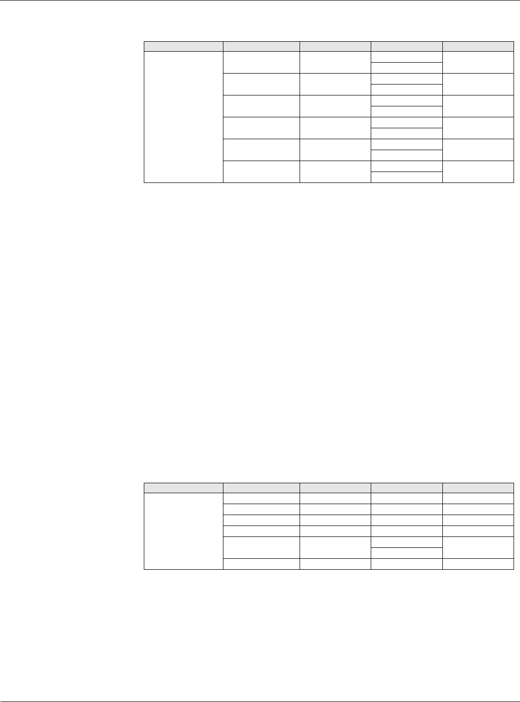
Table 7: Flow Summary Menu
Menu Display Name Item Display Name Default Setting Range Password Level
Flow Summary Airflow = - NoFlow 6
Flow
Waterflow= - NoFlow 6
Flow
Water Pump= - Off 6
On
Supply Fan= Off 6
On
Ret/Exh Fan= Off 6
On
VAV/FanOp= Off 6
On
Table 8: Supply Fan Speed Menu
Menu Display Name Item Display Name Default Setting Range Password Level
SAF Spd Control SAF Speed= - 0-100% 6
Speed Cmd= - 0-100% 6
Duct Press= - 0.0-5.0in 6
DuctSP Spt= 1.0in 0.2-4.0in 6
SAF Ctrl= DSP DSP 6
Speed
Rem SAF Cap= 25% 0-100% 6