
Instruction manual


Table Of Contents
- Introduction
- Using the Keypad/Display
- Keypad/Display Menu Structure
- System Summary Menu
- Standard Menus
- System Menu
- Occupancy Menu
- Temperature Menu
- Flow Summary Menu
- Supply Fan Speed Menu
- Return/Exhaust Fan Speed Menu
- Cooling Menu
- Head Pressure Menu
- Evap Condensing Menu
- Economizer Menu
- Min OA Damper Menu
- Heating Menu
- Energy Recovery
- Dehumidification Menu
- Daily Schedule Menu
- One Event Schedule Menu
- Holiday Schedule Menu
- Optimal Start Menu
- Operating Hours Menu
- Extended Menus
- Unit Setup Menu
- Timer Settings Menu
- Time/Date Menu
- Supply Fan Setup Menu
- Return/Exhaust Fan Setup Menu
- Zone Temperature Setup Menu
- Compressor Setup Menu
- Head Pressure Setup Menu
- Chilled Water Setup Menu
- Economizer Setup Menu
- Design Flow Setup Menu
- Heating Setup Menu
- Dehumidification Setup Menu
- Alarm Out Configuration Setup Menu
- Alarm Limits Setup Menu
- Manual Control Menu
- LON/BACnetIP/BACnetMSTP Setup Menu
- Active Alarm Menu
- Alarm Log Menu
- Advanced Menus
- Unit Configuration Setup Menu
- Save/Restore Menu
- Alarm Delays Setup Menu
- Analog Input Status Menu
- Universal I/O Status Menu
- Digital Input Status Menu
- Digital Output Status Menu
- Adv Setup Settings Menu
- Adv Status Parameters Menu
- Alarms
- Operator’s Guide
- Determining Unit State
- Off Operating State
- Start Up Operating State
- Recirculating Operating State
- Heating
- Economizer
- Mechanical Cooling
- Determining Unit Status
- Determining Control Mode
- Determining Cooling Status
- Determining Heat Status
- Determining Economizer Status
- Determining Cooling Capacity
- Determining Heating Capacity
- Determining Supply Air Fan Capacity
- Determining RF/EF Capacity
- Determining Outside Air Damper Position
- Determining Emergency Mode
- Determining Application Mode
- Determining Occupancy Status
- Determining Occupancy Mode
- Determining Occupancy Source
- Unoccupied Operation
- Scheduling
- Temperature Control Configurations
- Heat/Cool Changeover
- Dehumidification
- Energy Recovery
- Outside Air Damper Control
- Outside Air Damper Control, Two Position
- Special Procedures for Units with WRV and More Than Two Circuits.
- Water Pump Control
- Cooling: Multistage
- Cooling: Modulating
- Heating Control
- Modulating
- Min DAT
- Indoor Air Fan - On/Off Control
McQuay OM 920 13
Keypad/Display Menu Structure
DAT Clg Spt is a status only item which indicates the temperature that the DAT should be
maintained at when it is in the cooling mode of operation.
DAT Htg Spt is a status only item which indicates the temperature that the DAT should be
maintained at when in the heating mode of operation.
Min DAT Limit is a status only item which indicates the discharge air low limit temperature
on CAV zone control units. Heating will be activated to maintain this setting when the
discharge temperature falls below it during the Fan Only operating state. On VAV or CAV
discharge control units, the minimum discharge temperature limit is the DAT Clg Spt.
SAFSpeed is a status only item which indicates the capacity of the supply air fan.
DSP is a status only item which displays the current duct static pressure reading.
DuctSP Spt= is a status only item which indicates the duct static pressure set point used for
controlling the VFD for the supply air fan. The VFD is modulated to maintain the duct
pressure at this value.
RF/EF Speed is a status only item indicating the capacity of the return fan/exhaust air fans.
BSP is a status only item which displays the current building static pressure reading.
BldgSP Spt is a status only item which indicates the building static pressure set point used for
controlling the return/exhaust fan VFD. The return/exhaust fan VFD is modulated to maintain
the building static pressure sensor input to this value.
OA Temp is a status only item which displays the current temperature reading from the unit
mounted outdoor air temperature sensor. This sensor is standard on all units.
EW Temp is a status only item that displays the current temperature reading from the unit
mounted entering water temperature sensor. The sensor is standard on all water-cooled units.
Rel Humidity is a status only item that displays the current relative humidity reading from the
optional humidity sensor.
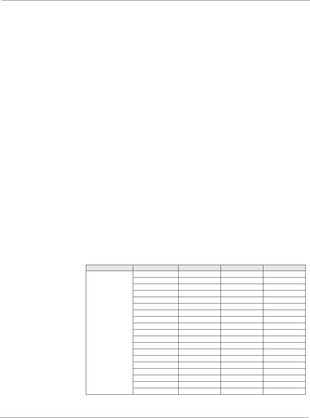
Standard Menus
The Standard Menus are menu items that control the unit's day to day operation. The menus
provide information about the units operation and its control parameters. Accessing the
Standard Menus requires the operator to enter the four-digit level 6 password, (5321) using the
keypad buttons located on the controller interface.
Table 3: Standard Menus
Menu Display Name Item Display Name Default Setting Range Password Level
Standard Menu System 6
Occupancy 6
Temperatures 6
Flow Summary 6
SAF Spd Control 6
RF/EF Spd Control 6
Cooling 6
Head Pressure 6
Evap Condensing 6
Economizer 6
Min OA Damper 6
Heating 6
Energy Recovery 6
Dehumidification 6
Daily Schedule 6
One Event Schedule 6
Holiday Schedule 6
Optimal Start 6
Operating Hours 6