
Instruction manual

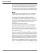


Table Of Contents
- Introduction
- Using the Keypad/Display
- Keypad/Display Menu Structure
- System Summary Menu
- Standard Menus
- System Menu
- Occupancy Menu
- Temperature Menu
- Flow Summary Menu
- Supply Fan Speed Menu
- Return/Exhaust Fan Speed Menu
- Cooling Menu
- Head Pressure Menu
- Evap Condensing Menu
- Economizer Menu
- Min OA Damper Menu
- Heating Menu
- Energy Recovery
- Dehumidification Menu
- Daily Schedule Menu
- One Event Schedule Menu
- Holiday Schedule Menu
- Optimal Start Menu
- Operating Hours Menu
- Extended Menus
- Unit Setup Menu
- Timer Settings Menu
- Time/Date Menu
- Supply Fan Setup Menu
- Return/Exhaust Fan Setup Menu
- Zone Temperature Setup Menu
- Compressor Setup Menu
- Head Pressure Setup Menu
- Chilled Water Setup Menu
- Economizer Setup Menu
- Design Flow Setup Menu
- Heating Setup Menu
- Dehumidification Setup Menu
- Alarm Out Configuration Setup Menu
- Alarm Limits Setup Menu
- Manual Control Menu
- LON/BACnetIP/BACnetMSTP Setup Menu
- Active Alarm Menu
- Alarm Log Menu
- Advanced Menus
- Unit Configuration Setup Menu
- Save/Restore Menu
- Alarm Delays Setup Menu
- Analog Input Status Menu
- Universal I/O Status Menu
- Digital Input Status Menu
- Digital Output Status Menu
- Adv Setup Settings Menu
- Adv Status Parameters Menu
- Alarms
- Operator’s Guide
- Determining Unit State
- Off Operating State
- Start Up Operating State
- Recirculating Operating State
- Heating
- Economizer
- Mechanical Cooling
- Determining Unit Status
- Determining Control Mode
- Determining Cooling Status
- Determining Heat Status
- Determining Economizer Status
- Determining Cooling Capacity
- Determining Heating Capacity
- Determining Supply Air Fan Capacity
- Determining RF/EF Capacity
- Determining Outside Air Damper Position
- Determining Emergency Mode
- Determining Application Mode
- Determining Occupancy Status
- Determining Occupancy Mode
- Determining Occupancy Source
- Unoccupied Operation
- Scheduling
- Temperature Control Configurations
- Heat/Cool Changeover
- Dehumidification
- Energy Recovery
- Outside Air Damper Control
- Outside Air Damper Control, Two Position
- Special Procedures for Units with WRV and More Than Two Circuits.
- Water Pump Control
- Cooling: Multistage
- Cooling: Modulating
- Heating Control
- Modulating
- Min DAT
- Indoor Air Fan - On/Off Control

McQuay OM 920 113
Operator’s Guide
The unit remains in either Heating or Minimum DAT Control for the duration of the
LowFireTime (Default = 240 seconds). The gas heating valve does not modulate from its
calculated value to allow the temperature to approach equilibrium with modulating gas heating
valve at a fixed position.
The unit reverts to normal modulation of the gas heating valve when the LowFireTime has
elapsed since the unit entered Heating or MinDAT.
Return Air Units
When the unit enters the Heating operating state, the controller first holds the gas valve at the
minimum fire position (5% or 33% depending on the burner model) until the Heating
Interstage Timer expires. Then, the controller modulates the gas valve to maintain the
discharge air temperature at the Discharge Heating Set Point.
Discharge Air Temperature Setpoint Reset - Heating
The Heating DAT Setpoint may be reset for units with DAT Heating Control. The Discharge
Air Temperature Setpoint will never be set below the Minimum DAT Heating Setpoint or
above the Maximum DAT heating Setpoint on the Heating Reset menu. The reset type may be
set to one of the following:
• None Discharge Heating Spt = User Adjustable
• Network Discharge Heating Spt = Network DAT Htg Setpoint (NetDAClSP) when it is valid
• Space Discharge Heating Spt is based on the Space Sensor
• Return Discharge Heating Spt is based on the Return Air Sensor
• OAT Discharge Heating Spt is based on the Outdoor Air Temperature
• Ext mA Discharge Heating Spt is determined by a 0-20 or 4-20 mA signal
• Ext V Discharge Heating Spt is determined by a 0-10 or 2 - 10 VDC signal
Reset reverts from Return to None when a Return Air Sensor opens or shorts. Reset reverts
from Space to None when a Space Sensor opens or shorts. Reset reverts from OAT to None
when an Outdoor Air Sensor opens or shorts.
When Space, Return, OAT, Ext mA, or Ext V is selected, the Discharge Heating Spt equals the
Max Htg Spt when the selected value equals the Max Htg Spt @ value. Similarly, the
Discharge Heating Spt equals the Min Htg Spt when the selected value equals the Min Htg Spt
@ value.
When Space, Return, or OAT is selected, it only makes sense for the DAT Heating setpoint to
decrease as the selected temperature increases as shown in the graph below.
When Ext mA is selected, the values “Min Htg Spt @” and “Max Htg Spt @” are entered as
mA values. When Ext VDC is selected, the values “Min Htg Spt @” and “Max Htg Spt @”
are entered as VDC values.
If Ext mA or Ext V is selected as the type of reset, the Min Htg Spt @ value may be set above
the Max Htg Spt @ value to cause a decrease in the DAT setpoint as the external signal or the
Min Htg Spt @ value may be set below the Max Htg Spt @ value to cause an increase in the
DAT setpoint as the external signal increase.
When ever the Clg Reset Type or Engineering Units is changed, the Min Clg Spt @ and Max
Clg Spt @ values revert to default values as follows:
• None: Min Clg Spt @=0NA, Max Clg Spt @=100NA
• Network: Min Clg Spt @=0NA, Max Clg Spt @=100NA
• Space, Return: Min Clg Spt @=73.0F, Max Clg Spt @=71.0F
• OAT: Min Clg Spt @=90.0F, Max Clg Spt @=70.0F
• ExtmA: Min Clg Spt @=4.0mA, Max Clg Spt @=20.0mA
• ExtVDC: Min Clg Spt @=0.0V, Max Clg Spt @=10.0V