
Instruction manual
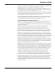


Table Of Contents
- Introduction
- Using the Keypad/Display
- Keypad/Display Menu Structure
- System Summary Menu
- Standard Menus
- System Menu
- Occupancy Menu
- Temperature Menu
- Flow Summary Menu
- Supply Fan Speed Menu
- Return/Exhaust Fan Speed Menu
- Cooling Menu
- Head Pressure Menu
- Evap Condensing Menu
- Economizer Menu
- Min OA Damper Menu
- Heating Menu
- Energy Recovery
- Dehumidification Menu
- Daily Schedule Menu
- One Event Schedule Menu
- Holiday Schedule Menu
- Optimal Start Menu
- Operating Hours Menu
- Extended Menus
- Unit Setup Menu
- Timer Settings Menu
- Time/Date Menu
- Supply Fan Setup Menu
- Return/Exhaust Fan Setup Menu
- Zone Temperature Setup Menu
- Compressor Setup Menu
- Head Pressure Setup Menu
- Chilled Water Setup Menu
- Economizer Setup Menu
- Design Flow Setup Menu
- Heating Setup Menu
- Dehumidification Setup Menu
- Alarm Out Configuration Setup Menu
- Alarm Limits Setup Menu
- Manual Control Menu
- LON/BACnetIP/BACnetMSTP Setup Menu
- Active Alarm Menu
- Alarm Log Menu
- Advanced Menus
- Unit Configuration Setup Menu
- Save/Restore Menu
- Alarm Delays Setup Menu
- Analog Input Status Menu
- Universal I/O Status Menu
- Digital Input Status Menu
- Digital Output Status Menu
- Adv Setup Settings Menu
- Adv Status Parameters Menu
- Alarms
- Operator’s Guide
- Determining Unit State
- Off Operating State
- Start Up Operating State
- Recirculating Operating State
- Heating
- Economizer
- Mechanical Cooling
- Determining Unit Status
- Determining Control Mode
- Determining Cooling Status
- Determining Heat Status
- Determining Economizer Status
- Determining Cooling Capacity
- Determining Heating Capacity
- Determining Supply Air Fan Capacity
- Determining RF/EF Capacity
- Determining Outside Air Damper Position
- Determining Emergency Mode
- Determining Application Mode
- Determining Occupancy Status
- Determining Occupancy Mode
- Determining Occupancy Source
- Unoccupied Operation
- Scheduling
- Temperature Control Configurations
- Heat/Cool Changeover
- Dehumidification
- Energy Recovery
- Outside Air Damper Control
- Outside Air Damper Control, Two Position
- Special Procedures for Units with WRV and More Than Two Circuits.
- Water Pump Control
- Cooling: Multistage
- Cooling: Modulating
- Heating Control
- Modulating
- Min DAT
- Indoor Air Fan - On/Off Control

102 McQuay OM 920
Operator’s Guide
Point 7 The discharge air temperature is again above the Effective Discharge Cooling Set
Point by more than half the Discharge Cooling Dead Band. Since the Cooling Interstage
Timer expired at Point 6, cooling is staged up. As a result, both DTA and DTB are zeroed and
the Cooling Interstage Timer is reset. Note that DTA and DTB are both zeroed since two
consecutive stage increase actions occurred. The discharge air temperature continues to rise,
however, because the cooling load is still increasing. Note that the elapsed time since the last
stage change in this illustration is 11.0 minutes.
Point 8 The Cooling Interstage Timer has expired. Since the discharge air temperature is still
above the Effective Discharge Cooling Set Point by more than half the Discharge Cooling
Dead Band, another stage-up occurs. As a result, DTA (Area K) is again zeroed out (DTB
remains zeroed) and the Cooling Interstage Timer is reset. The cooling load has leveled out,
and the discharge air temperature drops.
Point 9 The Cooling Interstage Timer has expired at the same time that DTB (Area M)
becomes equal to DTA (Area L). Therefore, cooling is staged down, the Cooling Interstage
Timer is reset and DTA is subtracted from both DTA and DTB. This zeros both DTA and DTB
since they are equal.
Figure 11: Cooling Interstage Timer
Staging - Zone Control
In the Cooling state, Compressor Stages are turned on and off to maintain the Control
Temperature close to the Zone Cooling Setpoint. Use of the Projected Control Temperature
reduces overshoot during cool down. See the Project Ahead section for a description of how
the Project Ahead Temperature is calculated.
When Dehumidification is active, Compressor stages are controlled to maintain the leaving
coil temperature between the minimum leaving coil setpoint and the maximum leaving coil
DAT Setpoint.
When the unit enters the Cooling state or dehumidification operation begins the unit goes
directly to Cooling Stage # 1 so that the first compressor is turned on immediately.
The number of Compressor Stages increases when:
• The time since the last stage change exceeds the Cooling stage timer AND
• Projected Control Temperature is greater than the Zone cooling Setpoint by more than half
the deadband AND