Operation and Maintenance Manual MicroTech III® Unit Controller for Applied Rooftop and Self-Contained Systems RAH, RCS, RDS, RDT, RFS, RPS, SWP, and SWT © 2008 McQuay International OM 920 Group: Applied Systems Part Number: OM 920 Date: October 2008
Contents Introduction .............................................................. 4 Getting Started ................................................... 5 Using the Keypad/Display ....................................... 6 Passwords .......................................................... 7 Navigation Mode................................................. 8 Edit Mode ........................................................... 8 Service Timers....................................................
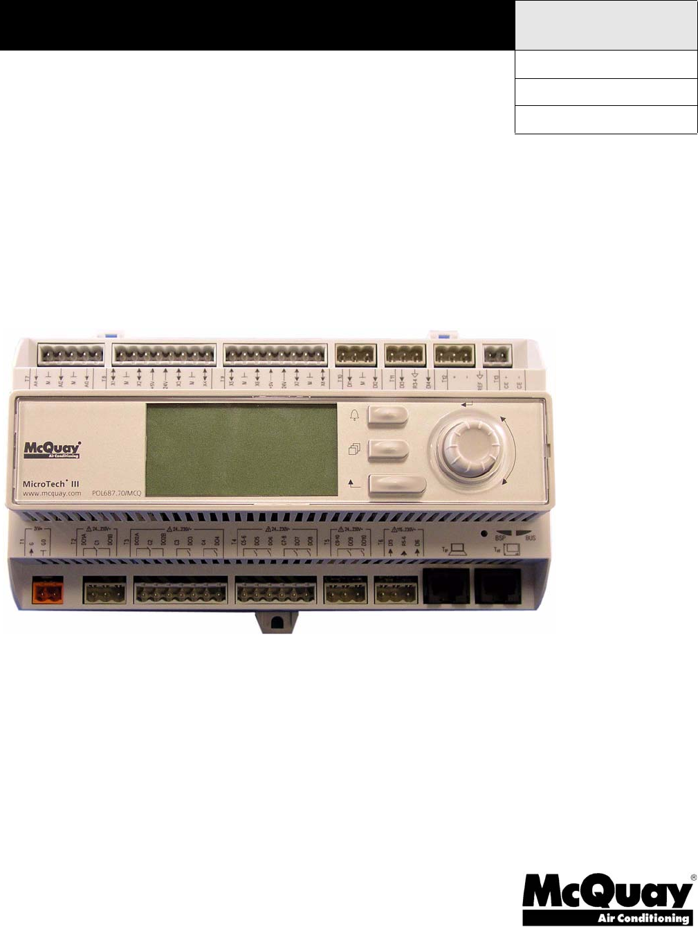
Introduction Introduction This manual provides information regarding the MicroTech III control system. It specifically describes the operation and programmable options for units with constant air volume (CAV) control and variable air volume (VAV) control. The MicroTech III Controller is a self contained device that is capable of complete, standalone operation. Information in the controller can be displayed and modified by using the keypad/display in the units main control panel.
Introduction WARNING Excessive moisture in the control panel can cause hazardous working conditions and improper equipment operation. When servicing this equipment during rainy weather, the electrical components in the main control panel must be protected from the rain. CAUTION Extreme temperature hazard. Can cause damage to system components. The MicroTech III controller is designed to operate in ambient temperatures from -20°F to 125°F. It can be stored in ambient temperatures from -40°F to 140°F.
Using the Keypad/Display Using the Keypad/Display The keypad/display consists of a 5-line by 22 character display, three keys and a “push and roll” navigation wheel. There is an Alarm Button, Menu (Home) Button, and a Back Button. The wheel is used to navigate between lines on a screen (page) and to increase and decrease changeable values when editing. Pushing the wheel acts as an Enter Button.
Using the Keypad/Display Passwords When the keypad/display is first accessed, the Home Key is pressed, the Back Key is pressed multiple times, or if the keypad/display has been idle for the Password Timeout timer (default 10 minutes), the display will show a “main” page where the user can enter a password or continue without entering a password. The three password levels available are Level 2, Level 4, and Level 6, with Level 2 having the highest level of access.
Using the Keypad/Display Navigation Mode In the Navigation Mode, when a line on a page contains no editable fields all but the value field of that line is highlighted meaning the text is white with a black box around it. When the line contains an editable value field the entire line is inverted when the cursor is pointing to that line. When the navigation wheel is turned clockwise, the cursor moves to the next line (down) on the page.
Using the Keypad/Display Manual Control A user may manually control outputs to check operation of components when Manual Control is set to ManCtrl. When Manual Control is set to ManCtrl, the unit is disabled and the unit is shut down in the normal manner if it is operating. Outputs listed in the Manual Control menu of the Keypad/Display section can then be controlled directly until Manual Control is set to Normal.
Keypad/Display Menu Structure Keypad/Display Menu Structure The following is a description of the MicroTech III menu structure. These menus and items can all be displayed with the keypad/display. Menu items displayed will change based on the selected unit configuration. Keypad/display menus are divided into 1) System Summary menu - password required. 2) Standard menu - password not required. 3) Extended Menu higher level password required. 4) Advanced Menu - requires the highest level password.
Keypad/Display Menu Structure McQuay OM 920 11
Keypad/Display Menu Structure System Summary Menu Menus in the System Summary category contain basic unit operating status and control set point parameters. The items shown in the System Summary Menu are Read Only and are not adjustable from this menu. The following are brief descriptions of the System Summary category menus and items. No password is required to view the System Summary Menu.
Keypad/Display Menu Structure DAT Clg Spt is a status only item which indicates the temperature that the DAT should be maintained at when it is in the cooling mode of operation. DAT Htg Spt is a status only item which indicates the temperature that the DAT should be maintained at when in the heating mode of operation. Min DAT Limit is a status only item which indicates the discharge air low limit temperature on CAV zone control units.
Keypad/Display Menu Structure System Menu The “System” menu provides a summary of basic unit status and control items. This menu summarizes the current operating state of the unit, giving the operating state the unit is in, along with the current capacity level of that operating state.
Keypad/Display Menu Structure Unit State is a status only item which indicates the state of operation in which the unit is currently operating. Unit Status is a status only item which indicates the current operating status. Ctrl Mode is an adjustable item which allows the unit to be set for off, auto heating/cooling operation, cooling only, heating only, and fan only. Clg Status is a status only item which indicates whether or not mechanical cooling is currently allowed.
Keypad/Display Menu Structure Occupancy Menu Menus in the Occupancy menu contain status and control items that relate to unit occupied/unoccupied operation.
Keypad/Display Menu Structure Temperature Menu Menus in the Temperatures menu contain unit temperature status information. Table 6: Temperature Menu Menu Display Name Item Display Name Default Setting Range Password Level Temperatures Control Temp= Disch Air= Return Air= Space Temp= OA Temp= EFT/LC Temp= EW Temp= Mixed Air= - -50.0-200.0°F -50.0-250.0°F -20.0-200.0°F -0.0-150.0°F -50.0-200.0°F -50.0-250.0°F -50.0-150.0°F -50.0-250.
Keypad/Display Menu Structure Flow Summary Menu Table 7: Flow Summary Menu Menu Display Name Item Display Name Default Setting Range Password Level Flow Summary Airflow = - 6 Waterflow= - Water Pump= - NoFlow Flow NoFlow Flow Off On Off On Off On Off On Supply Fan= Ret/Exh Fan= VAV/FanOp= 6 6 6 6 6 Airflow is a status only item that indicates whether or not discharge airflow is detected.
Keypad/Display Menu Structure SAF Ctrl is an adjustable parameter used to select how the supply fan is to be controlled. The supply fan can be controlled by supply air fan by duct pressure or by a percentage of supply air fan speed from 25% to 100%. The speed option is typically used with a building automation system. Remote SF Cap is an adjustable item for setting the supply fan speed by the keypad or by a network control signal.
Keypad/Display Menu Structure Cooling Menu Table 10: Cooling Menu Menu Display Name Item Display Name Default Setting Range Password Level Cooling Zone Clg Spt= Unocc Clg Spt= DAT Clg Spt= Min Clg Spt= Min Clg Spt @ 72.0°F 85.0°F 55.0°F 55.0°F 0/ NA 6 6 6 6 6 Clg Reset= None Max Clg Spt= Max Clg Spt @ 65.0°F 100/ NA 0.0-100.0°F 40.0-100.0°F 40.0-100.0°F 40.0-100.0°F 0-100/ NA °F °C mA % None Ntwrk Space Return OAT ExtmA ExtV Airflow 40.0-100.
Keypad/Display Menu Structure Max Clg Spt = 65.0 F Max Clg Spt @ = 35% Based on the above, the unit will have a discharge air temperature setpoint of 55.0 F from 80% to 100% of the airflow. Figure 5: Cooling Setpoint Head Pressure Menu The Head Pressure menu contains parameters that are used to maintain head pressure control.
Keypad/Display Menu Structure Evap Condensing Menu Table 12: Evap Condensing Menu Menu Display Name Item Display Name Default Setting Range Password Level Evap Condensing Cond Fan Spd= CFan Spd Cmd= Min Fan Speed= Stage Time= Sump Temp= Min Sump T= Max Sump T= Sump Dump Spt= Pump Status= 25% 10min 75.0°F 85.0°F 3-5.0°F - 6 6 6 6 6 6 6 6 6 Smp Pmp Delay= Conductivity= Dophin System= 30s No 0-100% 0-100% 0-100% 0-100min -50.0-150.0°F 0.0-100.0°F 0.0-100.0°F 0.0-100.
Keypad/Display Menu Structure Economizer Menu Table 13: Economizer Menu Menu Display Name Item Display Name Default Setting Range Password Level Economizer Economizer Pos= DAT Clg Spt= Min OA Pos= Chgover Temp= EWT Diff= 55.0°F 55.0°F 3.0d°F 0-100% 40.0-100.0°F 0-100% 0.0-100.0°F 0.0-10.0d°F 6 6 6 6 6 Economizer Pos is a status only item that is used to indicate percentage that the economizer dampers/waterside economizer valve is open.
Keypad/Display Menu Structure Min OA Damper Menu Table 14: Min OA Damper Menu Menu Display Name Item Display Name Default Setting Range Password Level Min OA Damper Min OA Pos= Vent Limit= DCV Limit= Min OA Reset= 20% 10% None 6 6 6 6 DesignFlow= Yes OA @ MinV/mA= OA @ MaxV/mA= Min V/mA= 0% 100% 0.0/ V Max V/mA= 10.0/ V PPM @DCV Lmt= PPM @Vnt Lmt= PPM= Min PPM= Max PPM= V/A @Min PPM= 800ppm 1000ppm 0ppm 2000ppm 0.0/ V V/A @Max PPM= 10.
Keypad/Display Menu Structure Min OA Reset is an adjustable item that sets the type of minimum OA damper position reset to be used. When this is set to “None” the Min OA Pos= parameter is set to the Ventilation Limit. When this is set to “Network,” “Ext VDC,” “Ext mA,” “IAQ VDC,” or “IAQ mA” then the Min OA Pos= parameter varies from the Ventilation Limit down to the Demand Control Ventilation Limit as the reset signal goes from its maximum to minimum value.
Keypad/Display Menu Structure Heating Menu The Heating menu provides a summary of the control parameters for units with heating. The unit's heating mode of operation is controlled by the control temperature and the heating setpoint temperature. The unit goes into the heating mode of operation by analyzing the control temperature. The control temperature can be return temperature, space temperature or outside air temperature.
Keypad/Display Menu Structure Min DAT Limit is a status only item which indicates the discharge air low limit temperature on CAV zone control units. Heating will be activated to maintain this setting when the discharge temperature falls below it during the Fan Only operating state. On VAV or CAV discharge control units, the minimum discharge temperature limit is the DAT Clg Spt. Occ Heating is an adjustable item which enables and disables the “daytime” heating mode of operation.
Keypad/Display Menu Structure Dehumidification Menu Table 17: Dehumidification Menu Menu Display Name Item Display Name Default Setting Range Password Level Dehumidification Dehum Status= - 6 Rel Humidity= Dewpoint= Dehum Method= None RH Setpoint= Dewpoint Spt= Reheat Spt= Reheat Cap = 50% 50°F - Disabled Enabled 0-100% -50-150°F None Rel Hum DewPt 0-100% 0-100°F 40.0-100.
Keypad/Display Menu Structure One Event Schedule Menu The One Event Schedule is used to set the start and stop times for one event. Table 19: One Event Schedule Menu Menu Display Name Item Display Name Default Setting Range Password Level One Event Schedule Beg= 00/00/00 @ 00:00 6 End= 00/00/00 @ 00:00 00/00/00-12/31/99 @ 00:00 – 23:59 00/00/00-12/31/99 @ 00:00 – 23:59 6 Holiday Schedule Menu The Holiday Schedule is used to set the start and stop times for up to 16 different holidays.
Keypad/Display Menu Structure Operating Hours Menu The Operating Hours menu gives a summary of the hours of operation for each of the supply fans, return/exhaust fans, compressors, heating and economizer operation.
Keypad/Display Menu Structure Accessing the Extended Menus requires the operator to enter the four-digit Level 4 password, (2526) using the keypad buttons located on the controller interface.
Keypad/Display Menu Structure Timer Settings Menu Table 25: Timer Settings Menu Menu Display Name Item Display Name Default Setting Range Password Level Timer Settings Service Time= Start Up= Recirculate= Zero OA Time= Tnt Override= Post Heat= Password= Low DAT= ClgStateDelay= Bypass Valve= 0min 180s 180s 0min 120min 0s 10min 6min 300s 300s 0-240min 1800s 3600s 0-240min 0300min 0-180s 3-30min 0-60min 0-600s 0-600s 4 4 4 4 4 4 4 4 4 4 Service Time is an adjustable item that sets the amount of time
Keypad/Display Menu Structure Time/Date Menu Table 26: Time/Date Menu Menu Display Name Item Display Name Time/Date Time= Date= Default Setting Range Password Level HH:MM:SS MM/DD/YYYY 4 4 Time = is an adjustable item that sets the current time. Date= is an adjustable item that sets the current date.
Keypad/Display Menu Structure Return/Exhaust Fan Setup Menu Table 28: Return/Exhaust Fan Setup Menu Menu Display Name Item Display Name Default Setting Range Password Level Ret/Exh Fan Setup BSP Ctrl Dly= BSP DB= BSP Period= BSP Gain= Max Spd Chg= Sup Fan Max= RF @ SF Max Sup Fan Min= RF @ SF Min= Min Speed= MinExStrtTime= MinExStopTime= MinExhOAPos= MinExhSAFCap= 30s 0.01in 5s 0.2 4% 100% 95% 30% 25% 5% 120s 120s 5% 10% 0-999s 0.0-0.1in 0-999s 0.0-100.
Keypad/Display Menu Structure Zone Temperature Setup Menu Table 29: Zone Temperature Setup Menu Menu Display Name Item Display Name Default Setting Range Password Level Zone Temp Setup Ctrl Temp Src= RAT 4 Use Tstat Spt= No Zone Clg DB= Clg Period= Clg Gain= Clg PAT= Max Clg Chg= Zone Htg DB= Htg Period= Htg Gain= Htg PAT= Max Htg Chg= 2.0d°F 60s 0.1 600s 5.0d°F 2.0d°F 60s 0.1 600s 5.0d°F RAT Space MAT OAT No Yes 0.0-10.0d°F 0-999s 0.0-100.0 0-999s 0.0-50.0d°F 0.0-10.0d°F 0-999s 0.0-100.
Keypad/Display Menu Structure Compressor Setup Menu Table 30: Compressor Setup Menu Menu Display Name Item Display Name Default Setting Range Password Level Compressor Setup Clg DB= Lead Circuit= 2.0°F #1 4 4 Staging Type= Standard Stage Time= CFanOut1 Spt= CFanOut2 Spt= CFanOut3 Spt= Cond Fan Diff= OAT Clg Lock= OATDiff= Min EWT= 5min 105°F 105°F 105°F 5°F 55°F 2d°F 55°F 1.0-10.
Keypad/Display Menu Structure Min EWT is an adjustable item that sets the minimum allowable entering water temperature.
Keypad/Display Menu Structure Chilled Water Setup Menu Table 32: Chilled Water Setup Menu Menu Display Name Item Display Name Default Setting Range Password Level Chilled Water Setup Clg DB= Clg Period= Clg Gain= Clg PAT= CW Max Chg= Stage Time= OAT Clg Lock= OATDiff= 2.0d°F 20s 1 40s 15% 5min 55°F 2°F 1.0-10.0d°F 0-999s 0.0-100.0 0-999s 0-100% 5-60min 0-100°F 0-10°F 4 4 4 4 4 4 4 4 Clg DB an adjustable item which sets a dead band around the discharge cooling setpoint parameter.
Keypad/Display Menu Structure Econo Max Chg is an adjustable item that sets the maximum value for an increase or decrease of the economizer actuator. Flush Econo is an adjustable item used to initiate the waterside economizer flush mode sequence. Econo Diff is an adjustable item which sets a differential above the EconChgovrT parameter. Economizer operation is disabled when the OA Temp parameter indicates a value above the EconChgovrT= parameter by more than this differential.
Keypad/Display Menu Structure Heating Setup Menu Table 35: Heating Setup Menu Menu Display Name Item Display Name Default Setting Range Password Level Heating Setup Htg DB= Htg Period= Htg Gain= Htg PAT= Htg Max Chg= Stage Time= OAT Htg Lock= OAT Diff= F&BP Method= 2.0d°F 60s 0.8 120s 10% 5min 55°F 2d°F OpenVlv 4 4 4 4 4 4 4 4 4 F&BP ChgOvrT= Warmup Period= Heat Up Delay= Hold Period= 37°F 240s 60s 240s 1.0-10.0°F 0-999s 0.0-100.
Keypad/Display Menu Structure Dehumidification Setup Menu Table 36: Dehumidification Setup Menu Menu Display Name Item Display Name Default Setting Range Password Level Dehum Setup RH DB= 2% 0-10% 4 Dewpoint DB= Reheat Period= Reheat Gain= Reheat PAT= RH Max Chg= RH Stg Time= Dehum Method= 2°F 10s 1 20s 16% 10 None 4 4 4 4 4 4 4 Dehum Ctrl= Occupied Sensor Loc= Return 2-10°F 0-999s 0.0-100.
Keypad/Display Menu Structure Mn Lvg Coil T is an adjustable item which is used to set the minimum leaving coil temperature (Default = 48°F). Mx Lvg Coil T is an adjustable item which is used to set the maximum leaving coil temperature (Default = 55°F). Min Reheat Spt is an adjustable item which is used to set the minimum DAT during dehumidification. Max Reheat Spt is an adjustable item which is used to set the maximum DAT during dehumidification.
Keypad/Display Menu Structure Alarm Limits Setup Menu The Alarm Limits menu is used to set the limits of the discharge air temperature sensor and the return air temperature sensor. Table 38: Alarm Limits Setup Menu Menu Display Name Item Display Name Default Setting Range Password Level Alarm Limits Hi Disch Temp= Lo Disch Temp= Hi Return Temp= 170°F 40°F 120°F 90-250°F -50-50°F 90-150°F 4 4 4 Hi Disch Alm is an adjustable item that sets the high temperature limit for the DAT sensor.
Keypad/Display Menu Structure Manual Control Menu The manual control of operation is a function that is used for operating the unit during a service call only. The unit must not be operated in this mode for any extended period of time.
Keypad/Display Menu Structure Table 39: Manual Control Manual Menu Display Name Item Display Name Default Setting Range Password Level Manual Control Htg Stg 5= Off 4 Htg Stg 6= Off Reheat Valve= Reheat Stage= ERec Wheel= 0% Off Off ER Whl Cmd= ERBP Dmpr Cl= 0% Off ERBP Dmpr Op= Off Cond Wtr Pump= Off Alm Output= Off FanOp= Off Off On Off On 0-100% Off Off On 0-100% Off On Off On Off On Off On Off On 4 4 4 4 4 4 4 4 4 4 Manual Ctrl is an adjustable item that puts the unit into manua
Keypad/Display Menu Structure CW Valve is an adjustable item used to manually drive the chilled water valve open and closed. ECond VFD is an adjustable item which is used to turn on/off the evaporative cooling condenser fan VFD. ECFan Spd Cmd is an adjustable item which is used to set the evaporative cooling condenser fan VFD speed position. EC Drn Valve is an adjustable item which is used to open/close the evaporative cooling drain valve.
Keypad/Display Menu Structure LON/BACnetIP/BACnetMSTP Setup Menu See the Installation & Maintenance Manuals below for detailed instructions IM 916 MicroTech III Rooftop unit controller - BACnet IP communications IM 917 MicroTech III Rooftop unit controller - BACnet MSTP communications IM 918 MicroTech III Rooftop unit controller - BACnet LON communications Active Alarm Menu All active alarms as well as the date and time that they were detected are displayed on the Active Alarm menu.
Keypad/Display Menu Structure Advanced Menus The Advanced Menus should only be accessed by trained service personnel. The Advanced Menus are menu items that are used to set up the unit for its specific application. Accessing the Advanced Menus requires the operator to enter the four-digit level 2 password, (6363) using the keypad buttons located on the controller interface.
Keypad/Display Menu Structure Table 43: Unit Configuration Menu Configuration Code Position Description Values (Default Bold) RTU SCU 4 Compressorized Cooling Configuration • • 5 Generic Condenser Stages Low Ambient 0 = None 1 = Generic Condenser 2 = 2Cmp/2Circ/3Stg 3 = 3Cmp/2Circ/4Stg 4 = 2Cmp/2Circ/2Stg 5 = 3Cmp/3Circ/3Stg_NoWRV 6 = 3Cmp/3Circ/3Stg_WRV 7 = 4Cmp/2Circ/4Stg 8 = 4Cmp/4Circ/4Stg_NoWRV 9 = 4Cmp/4Circ/4Stg_WRV A = 6Cmp/2Circ/6Stg B = 6Cmp/6Circ/6Stg_NoWRV C = 6Cmp/6Circ/6Stg_WRV 1 –
Keypad/Display Menu Structure Table 43: Unit Configuration Menu Configuration Code Position Description Values (Default Bold) RTU 17 Return/Exhaust Fan Capacity Control Method • 18 Second Duct Pressure Sensor 19 Entering Fan Temp Sensor 20 Energy Recovery 21 Cooling Circuit Type 22 Head Pressure Control 23 Bypass Valve Control 24, 25, 26 27 Unit Size Refrigerant Type 28 HGRH Type 0 = None 1 = Tracking 2 = Building Pressure 3 = Position 0 = No 1 = Yes 0 = No 1 = Yes 0 = None 1=ConstSpd
Keypad/Display Menu Structure Analog Input Status Menu The Analog Input Status Menu provides diagnostic information to qualified service personnel. The items listed in this menu will provide current status information of the Units analog inputs.
Keypad/Display Menu Structure Digital Input Status Menu The Digital Input Status Menu provides diagnostic information to qualified service personnel. The items listed in this menu will provide current status information of the controller's digital inputs.
Keypad/Display Menu Structure Table 49: Digital Output Status Menu McQuay OM 920 Menu Display Name Item Display Name Default Setting Range Password Level Digital Out Status MCB DO7= Off 2 MCB DO8= Off MCB DO9= Off MCB DO10= Off EMA DO1= Off EMA DO2= Off EMA DO3= Off EMA DO4= Off EMA DO5= Off EMA DO6= Off EMB DO1= Off EMB DO2= Off EMB DO3= Off EMB DO4= Off EMB DO5= Off EMB DO6= Off EMC DO1= Off EMC DO2= Off EMC-DO3= Off EMC-DO4= Off EMC DO5= Off EMC DO6= Of
Keypad/Display Menu Structure Adv Setup Settings Menu The Advanced Setup Settings Menu should only be accessed by trained service personnel. The Advanced Setup Settings Menu can be accessed when a level 2 password has been entered.
Keypad/Display Menu Structure Adv Status Parameters Menu The Advanced Status Parameters Menu provides diagnostic information to qualified service personnel. The items listed in this menu will provide current status information which may be used to diagnose system performance issues.
Alarms Alarms Alarms provide the user with information about abnormal conditions that affect unit operation. The cause of the alarm should be investigated and eliminated before the unit or any disabled equipment in it is placed back into service. Faults are conditions that are serious enough to shut down the unit. The alarm must be manually cleared to allow unit operation. Problems are conditions that result in some limitation of unit operation, but the unit is allowed to continue to operate.
Alarms Conductivity If the unit is equipped with a Dolphin system and the Conductivity value rises above the alarm setpoint value, the conductivity alarm occurs. When the alarm condition is corrected, the conductivity warning must be manually cleared through the unit keypad or via a network signal.
Alarms Sump Pump Fail On evaporative cooling units if the sump pump is turned on but the pump status input remains open after the Sump Pump Delay (default 30 seconds), the pump is turned off and cooling remains off for one cooling stage time period before the controller tries again. If this condition occurs three times between 2:00 AM of one day and 2:00 AM of the next day, the Sump Pump Fail problem occurs.
Alarms Entering Water Temperature Sensor Problem If the entering water temperature sensor (EWT) is present and either shorted or open circuited for longer than the Sensor Alarm Delay (default is 30 seconds), the EWT Sensor problem occurs. When the EWT Sensor problem occurs, waterside economizer cooling is disabled. Mechanical cooling is not locked out based on EWT. When the alarm condition is no longer present, the EWT Sensor problem automatically clears.
Alarms Faults Airflow Fault If differential pressure switch PC7 fails to detect airflow for longer than the airflow timer (default = 120 seconds) after the unit leaves the Startup operating state or any time afterward, while the unit is running, the Fan Fail fault occurs. When the Fan Fail fault occurs, the unit is shut down. It remains shut down until the Fan Fail fault is manually cleared through the unit keypad or via a network signal.
Alarms Control Temperature Fault If the temperature sensor (ZNT1, RAT, OAT, MAT) selected as the Control Temperature source is not reliable for longer than the Sensor Alarm Delay (Default= 30 seconds), a Control Temperature Fault occurs. When the Control Temperature Fault occurs, the unit is shut down. It remains shut down until the Control Temperature Fault is manually cleared through the unit keypad or via a network signal.
Operator’s Guide Operator’s Guide The following “Operator's Guide” sections provide information regarding the day-to-day operation of the MicroTech III Unit Controller. Topics covered are such common tasks as scheduling, displaying and clearing alarms, and setting the controller for manual operation. Figure 6: State Diagram The transition from any operating state to another is graphically represented in this figure.
Operator’s Guide In the Start Up state, the optional Fan Operation input is turned on to allow shut off dampers to be opened before any the Supply Fan is turned on. A Fan Op/VAV output may be selected as either the Fan Operation output or the VAV output via the keypad. The parameter is adjustable via the following path: Extended Menus/Unit Setup/VAV/FanOut. The outdoor dampers remain closed. The Supply Fan is turned on when the unit enters the Recirculation state.
Operator’s Guide OFF Fan Retry The unit operating state is Off Fan Retry when The Fan Retry conditions below indicate that the unit should be shutdown and restarted after airflow is lost. • The supply fan is controlled by a VFD • The airflow switch (PC7) is open AND the duct static pressure is less than ½ the duct static pressure setpoint • There are no active faults that would shut down the unit.
Operator’s Guide Heating The unit enters the Heating operating state when the Control Temperature falls below the zone heating setpoint by more than ½ the zone heating deadband. During the Heating operating state, the outdoor air dampers are either 100% open if the unit is a 100% outdoor air unit or controlled to the minimum outside air position. Cooling is disabled.
Operator’s Guide Determining Unit Status Unit Status is a status only item which indicates whether or not the unit is enabled and if not why. The current Unit Status can be viewed via the following path: Standard Menu/System/Unit Status. Enabled Unit operation has not been disabled for any of the following reasons. OFF Manual The unit operating state is Off Manual when the control mode is set to OFF via the keypad. The control mode can only be changed via the System menu on the keypad/display.
Operator’s Guide Heat Cool When the Control Mode is set to “Heat/Cool,” both cooling and heating operation are allowed to operate as required to maintain the cooling and heating set points. Auto When the Control Mode is set to “Auto,” the heat/cool, cool only, heat only, and fan only decision is determined by the network application mode parameter, which is set via a network signal as described below. The NetApp Mode parameter has no effect on unit operation unless the Control Mode is set to “Auto.
Operator’s Guide Determining Heat Status Htg Status is a status item which indicates whether or not heating is currently allowed. If heating is disabled, the reason is indicated. The current Heat Status can be viewed via the following path: Standard Menu/System/Htg Status.
Operator’s Guide Off Ambient The unit is configured for waterside economizer and the EWT exceeds the mixed air temperature minus the EWT differential set point. OR The unit is configured for airside economizer and the outdoor air temperature (OAT) is too high for operation. OR Unit is configured for waterside economizer and the Entering Water Temperature (EWT) sensor is unreliable. OR Unit is configured for airside economizer and the outdoor air temperature (OAT) sensor is unreliable.
Operator’s Guide Determining Outside Air Damper Position OAD/Econo Cap is a status only item which indicates the current outdoor air damper or economizer valve position. The current OAD/Econo Cap can be view via the following path: Standard Menus/System/OAD/Econo Cap. Determining Emergency Mode Emergency Mode is an adjustable only item which is normally used by a network system to shutdown the unit in an emergency situation.
Operator’s Guide Determining Occupancy Status Occupancy is a status item which indicates whether the unit is in an occupied, unoccupied or tenant override mode of operation. The current Occupancy status can be viewed via the following path: Standard Menus/Occupancy/Occupancy. The following are descriptions of the various “Occupancy” states. Occ The Occupancy parameter indicates “Occ” when the unit is in the occupied mode.
Operator’s Guide Determining Occupancy Mode Occ Mode is an adjustable item which sets the unit for manual occupied, unoccupied, tenant override or automatic operation. The parameter is adjustable via the following path: Standard Menu/Occupancy/Occ Mode. Occ When Occ Mode is set to “Occ,” the unit is manually placed in the occupied mode of operation. Unocc When Occ Mode is set to “Unocc,” the unit is manually placed in the unoccupied mode of operation.
Operator’s Guide Unoccupied Operation During Unoccupied operation the unit operates normally except that Min OA Pos is set to zero so that the damper is closed to the outdoor air. Unoccupied Dehumidification Dehumidification may be initiated in the unoccupied mode only if Dehumidification Control is set to Always instead of Occupied on the keypad.
Operator’s Guide Setting Controller Date and Time The controller uses the date and time to execute its internal scheduling functions. The current time and date will not be lost if the unit is turned off for up to forty-eight hours. The clock and date are settable from the keypad via the following path: Extended Menus/Time/Date. The time of day can be set by entering the hour (00-23), minute (00-59), and second (00-59) into three fields of the Current Time. Note that MicroTech III uses “military” time.
Operator’s Guide Temperature Control Configurations Temperature control is based on a Control Type that may be set to either Zone or DAT. When the Control Type is set to Zone temperature control, heating, compressors, and the economizer are controlled to maintain the temperature of the zone at a desired setpoint. This configuration is used on units equipped with constant volume supply fans. Compressors and heating stages are staged to maintain space or return temperature.
Operator’s Guide Control Temperature The “Control Temperature” is defined as the unit temperature input used to make the heat/cool changeover decision. This determines whether or not cooling or heating is enabled. The user may select Space Temperature, Return Temperature, or Outdoor Air Temperature for both Rooftop units and Self Contained units and the Mixed Air Temperature for Self Contained units. Normally either the Return or Space Temperature is selected as the Control Temperature.
Operator’s Guide OA/EWT Lockout Heating is disabled whenever the outdoor air temperature is greater than the Outdoor Air Ambient Heating Lockout Set Point. When the outdoor air temperature drops below the Outdoor Air Ambient Heating Lockout Set Point by more than the Heating Lockout Differential, heating operation is re-enabled. Cooling is disabled if outdoor air temperature or entering water temperature is too low for operation.
Operator’s Guide Post Heat Operation After leaving the Recirc or Heating operating state and entering either the Fan Only or Min DAT operating state, the unit performs “post heat” operation if the Post Heat Timer is set to a non zero value. “Post heat” operation occurs within the Fan Only or MinDAT operating state. During “post heat” operation, the VAV Box Output remains open (heat) while the discharge fan capacity is forced to a minimum value (default 25% speed for VFD).
Operator’s Guide Dehumidification Mechanical Cooling Control During Dehumidification, control of Mechanical Cooling is based on the following two editable values of the Leaving Coil Temperature setpoint. The Leaving Coil Temperature setpoint parameter is adjustable via the following path: Extended Menus/Dehum Setup/Mn Lvg Coil T or Mx Lvg Coil T.
Operator’s Guide Energy Recovery Energy recovery is provided by drawing outside air across half of an Enthalpy Wheel and drawing exhaust air across the other half. Latent and sensible heat is transferred from the hotter, moister exhaust air to the colder dryer outside air in winter. Latent and sensible heat is transferred from the hotter more moist outside air to the cooler dryer air exhaust in summer.
Operator’s Guide When there is a threat of frost on the enthalpy wheel, the wheel is slowed down or stopped so that less enthalpy transfer occurs and frosting of the wheel is avoided. Frosting can occur on the enthalpy wheel when the exhaust air leaving the wheel is saturated. This condition occurs when two lines intersect on a psychometric chart, and it does not occur when these two lines do not intersect. One of these lines is the Humidity Ratio versus the dry bulb temperature for saturated air.
Operator’s Guide Exhaust Fan A variable speed exhaust fan controlled by a VFD is provided for all Economizer units with either Constant Volume or VAV Supply Fans and on 100% Outside Air units with VAV Supply Fans. Either a constant volume exhaust fan or a variable speed exhaust fan controlled by a VFD may be provided on 100% Outside Air units with Constant Volume Discharge Fans.
Operator’s Guide Bypass Dampers (Not Applicable for 100% OA Units) • The Bypass Dampers are driven closed (Bypass Damper Closed output is energized) whenever the OA Damper position is less than or equal to the Minimum OA Position • The Bypass dampers are driven open (Bypass Damper Open output is energized) whenever the OA Damper Position exceeds the Minimum OA Damper Position by more that 3% Outside Air Damper Control Minimum Outside Air Damper Control Control of the dampers in the Economizer state is desc
Operator’s Guide Examples of typical Min OA reset schedules. If IAQ VDC is selected as the Min OA Reset, the Minimum OA Position is calculated based on a 0-10V CO2 sensor input. The CO2 level is expressed as Parts per Million. The minimum and maximum sensor input values (0-10V) and the corresponding minimum and maximum PPM values are user editable.
Operator’s Guide Example #2 Min OA reset type = EXT VDC If the requirement is to have the OA damper be at its minimum (DCV Limit) when the field supplied signal is at its minimum (0VDC) and to be at its maximum (Vent Limit) when the field supplied signal is at its maximum (10VDC), the controller would be set up as follow: • Vent Limit = 100% • DCV Limit = 10% • Min OA reset type = EXT VDC • Min V/mA = 0 • Max V/mA = 10 • OA@MinV/mA = 0% • OA@MaxV/mA = 100% In Figure 10, the Minimum OA Position would vary li
Operator’s Guide In Return Air applications, a two position damper is driven closed position when the Supply Fan is off, the unit is in the Recirculation state, Occupancy is set to Unocc, or the fan has been on for less than the Zero OA Time. As a result the OA dampers are driven closed in night setback, night setup, morning warm-up, and morning cool down situations. In Return Air applications, a two position is driven to the desired minimum open position in all other conditions.
Operator’s Guide Slave Control Slave control can not be selected unless a water economizer is installed. When the unit is configured for slave control, the Bypass Valve position is set to 100% minus the Economizer Valve Position except in the Manual Mode. This provides nearly constant flow of water through the unit regardless of the requirements of the economizer. When the unit is in Manual Control mode, the Bypass Valve and Economizer Valve are controlled independently.
Operator’s Guide • A waterside economizer is installed AND • Economizer operation is enabled. In Mechanical Cooling states, the Bypass Valve is open under all other circumstances. In the Economizer state, the Bypass Valve is normally closed. It is opened in the Economizer state only if: • The unit has an Airside economizer AND • ClgStatus= Enabled or Off Ambient AND • Economizer Position is greater than or equal to 95.
Operator’s Guide The Water Regulating Valve is driven closed in all states except the Fan Only, Economizer, and Mechanical Cooling states, and during Dehumidification. Before the unit will transition from the Fan Only to Cooling operating state when mechanical cooling is required, the water regulating valve is opened for an adjustable minimum to allow time for water to flow through the condenser before a compressor starts.
Operator’s Guide Water Pump Control The Pump output is in the on position if: • The Bypass Valve output is being driven Open OR • The Water Regulating Valve output is being driven Open OR • A waterside economizer is installed AND • The unit is in the Economizer state OR • The unit is the Mechanical Cooling state OR • The Unit is in the Start Initial state AND • Flush Mode is set to Yes OR • The unit has a waterside economizer and a Freeze Fault or Freeze Problem is active OR • The unit has a waterside econo
Operator’s Guide • If Circuit #1 is disabled, the staging sequence is set to Alt-1 after the stage timer, unless Comp #2 is already on. Then the switch to Alt-1 happens immediately. Maximum cooling stages is set to 1. • If Circuit #2 is disabled, the staging sequence is set to Std-1 if comp #1 has fewer hours than comp #3, and the staging sequence is set to Std-2 if comp #1 does not have fewer hours than comp #3, after the stage time. Maximum cooling stages is set to 2.
Operator’s Guide Three Equal Sized Compressors, Three Circuits, No WRV Only one sequence is provided so the user makes no selections • Total cooling stages = 3. • Maximum cooling stages is always set to 3. • The Staging sequence is the Standard sequence that contains the enabled Stage 1 Compressor with the fewest run hours. Compressors in disabled circuits are ignored when only enabled compressor run hours are compared.
Operator’s Guide Table 58: Standard Staging Staging Sequence Standard Staging Stage 1 Compressor Stage 2 Compressors StgdClgCap 33% Stage 3 Compressors 67% 100% Four Equal Sized Compressors, Two Circuits The user selects the following: 1. Staging Type = Standard or Alternate Staging 2. Lead Circuit = Auto, # 1 or # 2. • Total cooling stages = 4.
Operator’s Guide Four Equal Sized Compressors, Four Circuits, No WRV Only one sequence is provided so the user makes no selections • Total cooling stage = 4. • Maximum cooling stages is always set to 4. • The Staging sequence is the Standard sequence that contains the enabled Stage 1 Compressor with the fewest run hours. Compressors in disabled circuits are ignored when only enabled compressor run hours are compared. Maximum cooling stages is set to 4.
Operator’s Guide • Any compressor on a disabled circuit stays off if it is already off and is turned off if it is on. Table 62: Standard Staging Stage 1 Standard Staging Stage 2 Stage 3 Stage 4 Compressor Compressors Compressors Compressors 1 2 25% 1,4 2,3 50% 1,3,4 2,3,4 75% 1,2,3,4 1,2,3,4 100% Staging Sequence Std-1 Std-2 StgdClgCap Six Equal Sized Compressors, Two Circuits The user selects the following: 1. Staging Type = Standard or Alternate Staging 2. Lead Circuit = Auto, # 1 or # 2.
Operator’s Guide Table 64: Alternate Staging Staging Sequence Alt-1 Alt-2 Alt-3 Alt-4 Alt-5 Alt-6 StgdClgCap Stage 1 Stage 2 Comps Comps 1 2 3 4 5 6 17% 1,3 2,4 3,5 4,6 1,5 2,6 33% Alternate Staging Stage 3 Stage 4 Comps Comps 1,3,5 2,4,6 1,3,5 2,4,6 1,3,5 2,4,6 50% 1,2,3,5 1,2,4,6 1,3,4,5 2,3,4,6 1,3,5,6 2,4,5,6 67% Stage 5 Comps Stage 6 1,2,3,4,5 1,2,3,4,6 1,3,4,5,6 2,3,4,5,6 1,2,3,5,6 1,2,4,5,6 83% 1,2,3,4,5,6 1,2,3,4,5,6 1,2,3,4,5,6 1,2,3,4,5,6 1,2,3,4,5,6 1,2,3,4,5,6 100% Comps Six Equa
Operator’s Guide disabling and re-enabling the compressors or turning the unit off and on may be necessary to cause sequence changes. • The compressor sequence changes immediately if a circuit is disabled to keep either compressor # 1 or # 2 on. This will result is compressors being turned off and others being turned on in this emergency condition. • The same staging sequence is used whether a circuit is disabled or not.
Operator’s Guide Table 67: Standard Staging Staging Sequence Stage 1 Comps Stage 2 Comps Stage 3 Comps Std-1 Std-2 Std-3 Std-4 Std-5 Std-6 Std-7 Std-8 ClgCap 1 2 3 4 5 6 7 8 13% 1,2 1,2 3,4 3,4 5,6 5,6 7,8 7,8 25% 1,2,3 1,2,8 2,3,4 3,4,5 4,5,6 5,6,7 1,7,8 6,7,8 38% Standard Staging Stage 4 Stage 5 Comps Comps 1,2,3,4 1,2,7,8 1,2,3,4 3,4,5,6 3,4,5,6 5,6,7,8 1,2,7,8 5,6,7,8 50% 1,2,3,4,5 1,2,3,7,8 1,2,3,4,8 2,3,4,5,6 3,4,5,6,7 1,5,6,7,8 1,2,6,7,8 4,5,6,7,8 63% Stage 6 Comps Stage 7 Comps Stage 8
Operator’s Guide Eight Equal Sized Compressors, Eight Circuits, WRV Only one sequence is provided so the user makes no selections. • Total cooling stages = 8. • Maximum cooling stages is always set to 8. • If both circuit # 1 and circuit # 2 are enabled, the staging sequence is Std-1 if compressor # 1 has fewer hours than compressor # 2, and the staging sequence is Std-2 if compressor # 1 does not have fewer hours than compressor # 2. • If Circuit # 1 is disabled, the staging sequence is Std-2.
Operator’s Guide The number of compressor stages increases when: • The time since the last stage change exceeds the cooling stage timer AND • Discharge air temperature is greater than the Discharge Cooling Setpoint by more than half the deadband AND • The current cooling stage is less than the number of available stages AND • The last stage change was a stage up AND • Dehumidification is not active OR • The time since the last stage change exceeds the cooling stage timer AND • Discharge air temperature is g
Operator’s Guide The Degree Time Below Value and Degree Time Above value change whenever a stage change occurs. If the previous stage change was a stage up and the number of stages increases again, both Degree Time Above and Degree Time Below are set to zero. If dehumidification is active, both Degree Time Above and Degree Time Below are set to zero. If the previous stage change was a stage down and the number of stages decreases again, both Degree Time Above and Degree Time Below are set to zero.
Operator’s Guide Point 7 The discharge air temperature is again above the Effective Discharge Cooling Set Point by more than half the Discharge Cooling Dead Band. Since the Cooling Interstage Timer expired at Point 6, cooling is staged up. As a result, both DTA and DTB are zeroed and the Cooling Interstage Timer is reset. Note that DTA and DTB are both zeroed since two consecutive stage increase actions occurred.
Operator’s Guide • Control Temperature is greater than the Zone cooling setpoint by more than half the deadband AND • Discharge Air Temperature is greater than the minimum DAT cooling setpoint AND • The current cooling stage is less than the available number of stages AND • Dehumidification is not Active OR • The time since the last stage change exceeds the Cooling stage timer AND • Dehumidification is active AND • Leaving Coil Temp is greater then the maximum leaving coil setpoint AND • Current Stage is le
Operator’s Guide Cooling: Modulating Modulating Cooling Control: Chilled Water When the unit's cooling type is set to chilled water and is in the Cooling operating state, or in the dehumidification operating state the chilled water valve is modulated to maintain the discharge air temperature at the Discharge Cooling Set Point (or Leaving Coil Temperature if in the dehumidification operating state).
Operator’s Guide When Airflow is selected, the values “Min Clg Spt @” and “Max Clg Spt @” are entered as percentage values. When Ext mA is selected, the values “Min Clg Spt @” and “Max Clg Spt @” are entered as mA values. When Ext VDC is selected, the values “Min Clg Spt @” and “Max Clg Spt @” are entered as VDC values.
Operator’s Guide Evaporative Condensing Control (RTU) The evaporative condensing option for Rooftop units uses the heat absorbed by evaporating water as well as air drawn across a bank of tubes with refrigerant flowing through them to condense hot refrigerant to a liquid. Water is pumped from a sump beneath the condenser tubes to nozzles above the coil that spray water onto the bank of tubes.
Operator’s Guide In addition to the fans controlled by the VFD there are up to three staged condenser fan output that are controlled based on sump temperature. The condenser fan outputs controlled by these outputs are mechanically prevented from operating when no compressors on that circuit are operating. When compressors are operating on both circuits, the number of fans operating on the two circuits is the same since these output are wired to turn on the same fans on each circuit.
Operator’s Guide Heating Control Entering Heating Operating State The unit enters the Heating operating state from the Fan Only operating state when the control temperature falls below the Zone Heating Set Point by more than half the Zone Heating Dead Band. The unit transitions from heating to Fan only when the control temperature rises above the Zone Heating Set Point by more than half the Zone Heating Dead Band.
Operator’s Guide • DAT is greater than the effective DAT setpoint (DAT staging) or the MIN DAT limit (MinDAT staging) by ½ the deadband OR • The current heating stage is more than the number of available heating stages The unit enters the Min DAT operating state during occupied operation when neither cooling nor heating is required based on the unit heat/cool changeover function but the discharge air temperature falls below a minimum discharge temperature limit by more than ½ the deadband.
Operator’s Guide Gas Heat When a unit is equipped with modulating gas heating and is in the Heating operating state, the gas valve is modulated to maintain the discharge air temperature at the Discharge Heating Set Point. Differences in the control of modulating gas heat are described in the following sections. On units equipped with modulating gas heat, the Discharge Heating Set Point is limited according to a maximum heat exchanger temperature rise limit.
Operator’s Guide After completion of the FSG prepurge period there will be a 10 second trial for ignition during which terminal #8 (combination gas valve - GV1) and terminal #10 (ignition transformer - IT) will be energized.
Operator’s Guide Special Start Sequence for 100% Outdoor Air units with Gas Heat A special start sequence is used for units 100% outdoor air units with gas heat. The special start sequence applies to both Zone Control and DAT control units. If heat is required at unit startup, the furnace enters a special burner startup sequence as the unit enters its Startup operating state.
Operator’s Guide The unit remains in either Heating or Minimum DAT Control for the duration of the LowFireTime (Default = 240 seconds). The gas heating valve does not modulate from its calculated value to allow the temperature to approach equilibrium with modulating gas heating valve at a fixed position. The unit reverts to normal modulation of the gas heating valve when the LowFireTime has elapsed since the unit entered Heating or MinDAT.
Operator’s Guide An example of discharge temperature reset based on outdoor air temperature is illustrated in Figure 13 (Cooling Reset Type Flag is set to “OAT” in this example). When the current outdoor air temperature is greater than or equal to the Minimum Cooling Set Point Reset Value (90°F in this example), the Discharge Cooling Set Point is set equal to the Minimum Discharge Cooling Set Point (55°F in this example). This is shown as Point C in Figure 13.
Operator’s Guide Supply Fan Capacity Control (VAV) The speed of a modulating Supply Fan is controlled by an analog signal provided to the VFD. Supply Fan Capacity Control for a modulating fan is controlled to either: • Maintain the duct static pressure at a desired value OR • Maintain a fixed speed based on a signal provided via a network. The choice of control method, SF Cap Ctrl, may be set to Duct Press or Speed via the keypad.
Operator’s Guide Exhaust Fan - Speed Control When speed control is selected, the fan operates at the larger of its minimum speed or a value provided via a connected network or the keypad/display. This value reverts to zero when the unit is off and remains at that value after startup until a non zero value is written via the network or the keypad/display.
Operator’s Guide Fan Tracking Control For units with variable frequency drives, the return fan may be controlled such that the return fan speed tracks up and down with the supply fan speed. The user defines the position of the return fan with respect to the supply fan for minimum and maximum positions. When the supply fan is between the minimum and maximum positions, the fan varies proportionally between its minimum and maximum values. There are four adjustable parameters to define this relationship.
McQuay Training and Development Now that you have made an investment in modern, efficient McQuay equipment, its care should be a high priority. For training information on all McQuay HVAC products, please visit us at www.mcquay.com and click on training, or call 540-248-9646 and ask for the Training Department. Warranty All McQuay equipment is sold pursuant to its standard terms and conditions of sale, including Limited Product Warranty. Consult your local McQuay Representative for warranty details.