SERVICE GUIDE BOOK
MCQUAY Service Guide Book Table of Contents Table of Contents 1.0 MODEL NAME 1.1 2.0 3 Product Mainboard vs. Handset Matrix ............................... 4 G6 G7 G11 G17 GS01 APJ1 SLM3 SLM8 Sequential LCD Netware 3/3C Rooftop Panel Chiller Panel MC301 MC303 ............................... ............................... ............................... ............................... ............................... ............................... ............................... ..................
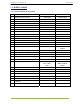
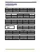
MCQUAY Service Guide Book Model Name 1.0 MODEL NAME 1.1 Product Name Description No.
MCQUAY Service Guide Book Conversion Table 2.0 CONVERSION TABLE 2.1 Conversion Table Capacity Btu/hr 1 1000 3.968 3412 MBH 0.001 1 0.004 3.412 kCal/Hr 0.252 252 1 860.04 kW 0.293 x 10⁻³ 0.293 1.162 x 10⁻³ 1 Pressure PSI kg/cm2 1 14.22 3.61 x 10⁻² 1.45 x 10⁻⁴ 0.07 1 2.538 x 10⁻³ 0.1 x 10⁻⁴ Flow Rate L/s 1 0.278 1000 0.063 0.472 Temperature °F = (1.8 x °C) + 32 °C = ° F − 32 1.8 Volume Area W.G. (in.) 27.7 394.08 1 0.004 m3/hr 3.6 1 3600 0.227 1.7 m3/s 0.001 0.278 x 10⁻³ 1 0.063 x 10⁻³ 0.
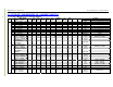
MCQUAY Service Guide Book Product Mainboard vs. Handset Matrix 3.0 PRODUCT MAINBOARD VS. HANDSET MATRIX 4 3.1 Product Mainboard vs. Handset Matrix Main Board Type No.
MCQUAY Service Guide Book Product Mainboard vs. Handset Matrix 5 Main Board (IC) Type No. CW FCU 13 14 15 16 17 18 19 Mini Chiller WSHP 20 21 22 23 W2 Model WM – GW Series CK – AW/MWH/CW Series CE – DW Series CE – EW Series CC – CW Series SB – BW Series AC – C Series AC 20 – 60C/CR AC 80 – 150C/CR 5AC 20 – 25C/CR 5AC 30 – 55C/CR 5WMWS – GR 5CKWS – AR/CR 5CCWS – CR WH – B Series WH 11 – 20B/BR WH 25 – 70B/BR MC1.
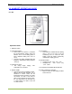
MCQUAY Service Guide Book Handset Operating Guide 4.0 HANDSET OPERATING GUIDE 4.1 G6 Operation Guide 1. “ON/OFF” Switch 5. Timer Setting Press button to activate the timer setting (from 1 hour to 15 hour) of the air conditioning unit. To cancel the timer setting, press the button continuously until the timer display goes off. 2. Temperature Setting • Press button to increase or decrease the set temperature.
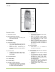
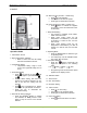
MCQUAY Service Guide Book Handset Operating Guide 4.2 G7 Operation Guide 10. Sleep Mode Setting • This function is available under COOL, HEAT & AUTO mode. • When it is activated in COOL mode, the set temperature will be increased 0.5°C after 30mins, 1°C after 1 hour and 2°C after 2 hours. • When it is activated in HEAT mode, the set temperature will be decreased 1°C after 30mins, 2°C after 1 hour and 3°C after 2 hours. 1. Transmission Source 2.
MCQUAY Service Guide Book Handset Operating Guide 4.3 G11 8. Sleep Mode Setting • This function is available under COOL, HEAT and AUTO mode. • When the unit is operating under cooling mode, the set temperature is increased by 0.5°C after 30 minutes, 1°C after an hour, and 2°C after 2 hours. • When the unit is operating under heating mode, the set temperature is decreased by 1°C after 30 minutes, 2°C after an hour and 3°C after 2 hours. 9. Clock Time Setting • Press + button to increase the clock time.
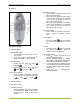
MCQUAY Service Guide Book Handset Operating Guide 4.4 G17 6a. Silent Function (For WM – J Series only) • Press for quiet operation. • Fan speed turn to minimum speed. • Press again to deactivate the function. 6b. Ionizer Function (For WM - G series only) • Press button to activate the negative ion function, which will refresh the indoor air effectively. 7. Sleep Mode Setting • This function is available under COOL, HEAT and AUTO mode. • When under cooling mode, the set temperature is increased by 0.
MCQUAY Service Guide Book Handset Operating Guide 4.5 GS01 1 2 3 6 4 5 7 13 9 12 8 11 10 Operation Guide Swing mode selection (for CK-E model) • Press SWING button for 4 seconds to enter field setting mode. • While in field setting mode, it will only . show SWING MODE • Press temperature button to select rotation from Swing SWING MODE Mode 1 to Swing Mode 3. • There are 3 different SWING MODE, which are: 1. Transmission Source 2.
MCQUAY Service Guide Book • • Handset Operating Guide Any change of fan speed will deactivate this function. The Turbo function is unavailable for chilled water system and remote control function. with SWING MODE 8. OFF timer setting 9. Quiet function (model dependant) • Press for quiet operation. • Fan speed turn to minimum speed. • Press again to deactivate the function. • Any change of fan speed will deactivate this function. • The Silent function is unavailable for chiller water system. 10.
MCQUAY Service Guide Book Handset Operating Guide 4.6 APJ1 1 2 5 6 7 8 3 9 4 10 12 13 11 Operation Guide • 1. Transmission Source 2. LCD Display 3. ECONO button • ECON operation is a function which enables efficient operation by limiting the maximum power consumption value. • This function is useful for cases which attention should be paid to ensure a circuit breaker will not trip when the product runs along side other appliances. • Press button to start ECONO operation.
MCQUAY Service Guide Book • • Handset Operating Guide • The flap (horizontal blade) will begin to swing. To set the flap at desired position, press button when the flap has reached the desired position. The flap will stop moving. The symbol disappeared from the LCD. button. LCD. 13. CANCEL Button 10.
MCQUAY Service Guide Book Handset Operating Guide 4.7 SLM3 Operation Guide after 30 minutes, 1°C after 1 hour and 2°C after 2 hours. If it is activated under “HEAT” mode operation, the set temperature will be decreased 0.5°C after 30 minutes, 1°C after 1 hour and 2°C after 2 hours. 1. “ON/OFF” Switch 2. Temperature Setting • Setting range are between 16°C to 30°C (60°F to 80°F). 3. Operation Modes • Press the “mode” button for select the type of operating mode.
MCQUAY Service Guide Book Handset Operating Guide 4.8 SLM8 • • • While in field setting mode, it will only . show SWING MODE Press temperature button to select rotation from Swing SWING MODE Mode 1 to Swing Mode 3. There are 3 different SWING MODE, which are: Mode 1 Mode 2 Mode 3 SWING MODE will not activate unless SWING is activated. • If no mode changes within 4 seconds, unit will operate According to the selected SWING MODE . No.
MCQUAY Service Guide Book Handset Operating Guide • Set Event 1 and Event 2 Timers • Process for Timer ON and Timer OFF is the same. • Press and hold Timer ON/OFF key for 3 seconds to go into timer setting mode. (Icon ON 1 or OFF 1 will blink) • Press UP or DOWN to select Timer 1 or Timer 2 to set. (‘1’ blinking indicate that Timer 1 is currently selected, ‘2’ blinking indicate that Timer 2 is currently selected) • Press Timer ON/OFF key again to confirm.
MCQUAY Service Guide Book Handset Operating Guide 4.8 Sequential Controller 5. Temperature Setting • To set the desired room temperature, press or to increase or decrease the set temperature in the range of 16°C to 30°C. • Press both and simultaneously to toggle between °C and °F setting. 6. Time Setting Real time clock • Press the CLOCK key once to activate set clock mode. • Press again to disable set clock mode.
MCQUAY Service Guide Book Handset Operating Guide 1. 2. 3. 4. 5. 6. 7. 8.
MCQUAY Service Guide Book • Handset Operating Guide • This timer can be controlled separately through remote control as well as ON TIMER or OFF TIMER keys. Timer 3 can be set like timers 1 and 2 like above except the DAY setting is not provided as this timer setting is valid everyday. An indicator ‘3’ will display during the Event 3 timer setting mode. ‘ON’ or ‘OFF’ will blink at 0.5 sec interval during the timer setting.
MCQUAY Service Guide Book Handset Operating Guide Operating Guide 1. LCD Display • Upon power up of the unit, the LCD displays the main display screen 2000/01/0 Status Mode Set Temp [SAT] 6. ECS Button 7. Downward Button • Press the button once to view the Compressor(s) On, Off or Defrost Status. • Press the button again to view the temperature for Return Air and Outdoor Air.
MCQUAY Service Guide Book Handset Operating Guide 4.11 Chiller Panel Operating Guide • 1. LCD Display • Upon power up of the unit, the LCD displays the main display screen 01/01/2003 Status Mode Set Temp The panel can keep up to 20 faults/alarm warning records. 6. ECS Button • Press to exit to previous Menu. 12:00am 7. Downward Button • Press the button once to view the Compressor(s) On or Off status.
MCQUAY Service Guide Book Handset Operating Guide 4.12 MC301 Operating Guide 1. ON/OFF Operation • Press “ON/OFF” key, the unit will be ON or OFF, and “ON” or “OFF” will display on the LCD. 6. Auxiliary Heater Setting • Under “HEAT” or “FAN” mode, press “HEATER/SWING” key to active heater. (Only for heater unit). “HEATER” will display on LCD. 2. Temperature Setting • Use “▲” or “▼” keyboard to increase or decrease by 1 °C/°F, temperature range is 16-30 °C (61-86°F).
MCQUAY Service Guide Book Handset Operating Guide • 10. Reset • This key is used to reset the unit. 11. Timer Setting • Week timer setting: Include total 28 on/off timers, 7 days every week and 4 timers every day. • Single timer setting: It is active only on the same day that timer set when power on. It is inactive when timer is set at AM 00:00. It can be set at AM 00:00 if you want to cancel some timer setting. • Press “FAN” and “MODE” at one time, all timers setting can be cancelled.
MCQUAY Service Guide Book Handset Operating Guide 4.13 MC303 Operating Guide • 1. Address Register • After communication wire is completely connected, press “SETUP” key for 5s. Address will be automatically registered and a number from 60 to 0 will be shown on the display LCD. 2. View Actual Address • Press “MODE” key for 5s then press “▲” or “▼” to view all the units.
MCQUAY Service Guide Book Handset Operating Guide • 10. Indoor unit lock/unlock • Press “UNIT No.” key to enter the unit setting, then press “▲” or “▼” to choose the unit number to be set or choose “_ _” for group setting and press “ENTER” to confirm. After that, press “SLEEP” key 5s to lock the chosen unit, the symbol “ ” will display on LCD panel, any operation by LCD panel or remote controller is invalid. • To unlock the unit, press “SLEEP” key 5s, the symbol “ ” will disappear. • • 11.
MCQUAY Service Guide Book Controller Configuration 5.0 CONTROLLER SETTING 5.1 Auto Random Restart 5.2 Hot Keep Selection • Three selections available: a. Fan stop if indoor coil temperature < 30°C (OFF). b. Fan runs at low speed if indoor coil temperature < 30°C and stop if indoor coil temperature < 18°C (ON). c. Cycle of low fan running for 30s and fan off for 120s and repeat (INTERVAL). • Shorted at JH/JP1/J_LST jumper at main board for auto restart (supplied).
MCQUAY Service Guide Book Controller Configuration L2 Models L208A / LWS2.0 models Two selections are available: There are 2 tables setting for HT_KP & MODEL jumpers as shown as below. a. Fan ON: - If the indoor coil temperature > 40°C, the indoor fan will run at speed. - If the indoor coil temperature crosses 37°C, the indoor fan will run at low speed. - If the indoor coil temperature <18°C, the indoor fan will stop. b.
MCQUAY Service Guide Book Controller Configuration 5.3 Sequential Board (SQ2.0) Dip switch setting of sequential controller are as the following: Dip switch 3 Off On Off On a. Default b. 0.5°C c. 1.0°C d. 1.5°C Dip switch 4 Off Off On On Note: 1.5°C only valid for 2 and 3 compressors model. For 4 compressors model, maximum allowed is 1.0°C.
MCQUAY Service Guide Book Controller Configuration 6. Defrost Option Select whether compressor will turn off or remain on when 4WV changes at beginning of defrost cycle. Dip switch 8 Off On (C2.4 spec) a. Compressor off b. Compressor on 7.
MCQUAY Service Guide Book Controller Configuration 5.4 Chilled Water Fan Coil Unit (W1V3) The standard W1V3 board comes with a VALVE jumper. The system can be configured as the jumper selection listed below: Mode Heatpump Cooling Only Application Valve Valve less Valve Valve less VALVE jumper √ X √ X Model: MCK 20-50AW, MCK 15-25BW, MCK 1020CW, MCM 20-50DW and MCC 10-60CW HEAT jumper √ √ X X 1. VALVE jumper is plugged into JVLV connector on the main board. 2.
MCQUAY Service Guide Book Controller Configuration 5.5 Chilled Water Fan Coil Unit (W2.0) The system operating modes can be configured via the following jumpers. For each jumper selected, the permissible operating modes are as follows: Jumper M1 M2 M3 M4 Configurati on 2 Pipes without Aux. Heater 2 Pipes with Aux.
MCQUAY Service Guide Book Controller Configuration 5.6 Hardware Setting – SLM8 There are 2 jumpers on SLM8 option to control the board function as shown in Picture below. 20-30C TURBO_ QUIET Summary of Hardware Setting as table below: Jumper 20-30C (Set Temp Range) Short 20°C – 30°C Open 16°C – 30°C (Default) Disable turbo & Enable turbo & quiet fan speed quiet fan speed (Default) * Only applicable to model with built in Turbo or Quiet features.
MCQUAY Service Guide Book Controller Configuration 6.0 CONVERSION CONFIGURATION 6.1 Auxiliary Heater Conversion U1.5 Heatpump with Auxiliary Heater To convert the standard U1.5 heatpump PCB to auxiliary heater application, the following components need to be added onto the PCB: 1. Heater relay (240V/20A) 2. Transistor, 2SC945 3. Diode, IN4003 RLY 8 D17 Q3 Board U1.
MCQUAY Service Guide Book Controller Configuration SB125 Heatpump with Auxiliary Heater To convert SB125 heatpump PCB to auxiliary heater application, only need to add one heater relay as shown below: 1. Place the JM Relay (240V/20A) on the RY_HTR location 2. Solder all the relay pins.
MCQUAY Service Guide Book Controller Configuration W2 Heatpump with Auxiliary heater To convert SB125 heatpump PCB to auxiliary heater application, the following components need to be added onto the PCB: 1. Shunt jumper 2. JM Relay 240VAC/ 20A Step 1:Place the shunt jumper at jumper header M2. M2 Step 2:1. Place the JM relay at RY_HTR location 2.
MCQUAY Service Guide Book Controller Configuration 6.2 Multi Split Conversion Cooling Only Model (L2.0 / L208A) Heatpump Models (L208A) MWM-G, MCK-A/B/C/E, MCM-E, MCC-C which are using L2 control board can be switched to multi split units without any modification needed. MCK-AR/BR/CR/ER, MCM-ER, MCC-CR The multisplit can be selected by using shunt jumper and short jumper header MODEL_KP between pin 1 & 2 as the picture shown below. Heatpump Model (L2.
MCQUAY Service Guide Book Controller Configuration 6.3 U1.5 Æ L208A Conversion 1. L2 08A Heat Pump PCB. 2. Room sensor, indoor coil sensor interconnector wire, outdoor coil sensor interconnector wire. 3. Inter-connector cable from main board to MCKA/AR panel. 4. Inter-connector cable from main board to MCKC/CR panel. 5. Intermediate board with 2 sets of cables, which is stick on the main board. 6. Inter-connector cable from main board to MCMD/DR assy. LED board. 7.
MCQUAY Service Guide Book Controller Configuration 6.4 WMF U1.4 to L2EF Conversion 3. only the display panel or On/Off switch board from U1.4 to L2EF or L2EF to U1.4. 1. The U1.4 PCB can be replaced directly by the new L2EF PCB because no modification needs to be done and the connector pins for both stepper motor and fan motor is still the same as U1.4. 4. For example, if the display panel for U1.
MCQUAY Service Guide Book Controller Configuration 6.5 SQ Board for Wiring up to 1000m Conversion Comparison of Sequential Main Board SQMB01 Before & After conversion: U8 J1 J2 Before IC:MAX1483 J1 removed J2 removed After Work Indication (WI): Step 1: Remove Jumper J1 and J2. Step 2: Solder PART 2051-MAX1483 (IC: MAX1483) to U8.
MCQUAY Service Guide Book Controller Configuration Sequential LCD conversion for wiring up to 1000m Work Indication (WI): Step 1: Dismantle the BACK cover of Sequential LCD. Step 2: Remove Jumper J1, J2. Step 3: Add Chip Resistor 1/10W 5% 200K to R8, R9 and R10. Step 4: Add PART 1000000030 IC: SMD MAX1438CSA to U4.
MCQUAY Service Guide Book Controller Configuration 6.6 Room Sensor on Netware 3 There is a temperature sensor located at TH1 on the Netware 3 controller board as shown in the picture below. The temperature sensor is optional and can be used as room sensor, so that room temperature reading will be captured from the temperature sensor on the wired controller Netware 3 instead of room sensor located at indoor PCB.
MCQUAY Service Guide Book Diagnosis 7.0 SERVICE DIAGNOSIS 7.1 LED Lights Diagnosis Table Wall Mounted F Series Cooling Only Model MWM 10/15/20/25F, 311 MWM 07/10/15/20/25F POWER SLEEP Board D2.
MCQUAY Service Guide Book Diagnosis Wall Mounted F Series Heat Pump Model MWM 10/15/20/25FR, 301R MWM 07/10/15/20/25FR, 311/301R COLD (Green) DRY (Orange) FAN HEAT (Green) (Red) Board U1.
MCQUAY Service Guide Book Diagnosis Wall Mounted G Series Model MWM 10/15/20/25G/GR SLEEP POWER Board L2.
MCQUAY Service Guide Book Diagnosis Wall Mounted J Series Model MWM 09/15J/JR SLEEP Board L2GSN Handset G17 TIMER POWER Error Code (Green/Red) (Red) / Green / Red / Red / Action (Orange) - Cooling mode - - Heating mode - - Green Auto mode in heating operation Auto mode in cooling operation - - Sleep mode On - - Fan mode On - - Dry mode On - Room air sensor contact loose / short 2 times E2 Indoor coil sensor contact open 3 times E3 Outdoor coil sensor contact open E
MCQUAY Service Guide Book Diagnosis Ceiling Cassette A / B / C Series Model Model MCK 20/25/30/40/50A/AR MCK 15/20/25B/BR MCK 10/15/20C/CR POWER (Green) TIMER Board U1.5 U1.5 U1.
MCQUAY Service Guide Book Diagnosis Ceiling Cassette A / B / C/ E Series Model Model MCK 20/25/30/40/50A/AR MCK 15/20/25B/BR MCK 10/15/20C/CR MCK 20/25/28/40/50E/ER POWER (Green) TIMER Board L208A L208A L208A L208A SLEEP (Orange) (Red) HEAT (Red) Handset G17 / SLM3 / Netware 3 / SLM8 G17 / SLM3 / Netware 3 / SLM8 GS01 / G17 / SLM3 / Netware 3 / SLM8 GS01 / G17 Error Code (SLM3 / Netware 3) Cooling mode - - Timer On - - Sleep mode On - - Heating mode - Auto mode in cooling operation Aut
MCQUAY Service Guide Book Diagnosis Ceiling Exposed D Series Model Model MCM 20/25/30/40/50D/DR Board U1.
MCQUAY Service Guide Book Diagnosis Ceiling Exposed D / E Series Model Model MCM 20/25/30/40/50D/DR MCM 15/20/25/28E/ER COOL (Green) DRY FAN (Orange) (Green) Board L208A L208A HEAT (Red) Handset G17 / SLM3 / Netware 3 / SLM8 G17 / SLM3 / Netware 3 / SLM8 Error Code (SLM3 / Netware 3) Operation / Faulty Indication - Cooling mode - - Dry mode - - Fan mode - - Heating mode - Auto mode in cooling operation Auto mode in heating operation E1 Room air sensor contact loose / short E2 Indo
MCQUAY Service Guide Book Diagnosis Chilled Water Fan Coil Unit Model MWM 05 – 25FW, 301W MCK 20 – 50AW/MWH MCK 15 – 25BW MCK 10 – 20CW MCM 20 – 50DW/CBW MCC 10 – 60CW MDB 75 – 150BW Board W1V3 W1V3 W1V3 W1V3 W1V3 W1V3 N/A Handset G7 / SLM3 / Netware 3 / SLM8 G7 / SLM3 / Netware 3 / SLM8 G7 / SLM3 / Netware 3 / SLM8 G7 / SLM3 / Netware 3 / SLM8 G7 / SLM3 / Netware 3 / SLM8 SLM3 / Netware 3 / SLM8 No Controller Self Diagnostic Table – W1V3 POWER LED Fault Indication / COOL LED Room sensor missing Blinks
MCQUAY Service Guide Book Diagnosis Water Source Split Unit – Wall Mounted G Series Model Model M5WMWS 10/15/20/25GR SLEEP POWER TIMER Board LWS2.
MCQUAY Service Guide Book Diagnosis Water Source Split Unit – Ceiling Cassette A / B / C Series Model Model M5CKWS 20/25/30/40/50AR M5CKWS 10/15/20CR POWER (Green) TIMER (Orange) HEAT (Red) Board LWS2.0 LWS2.
MCQUAY Service Guide Book Diagnosis Wall Mounted F Cooling Only Inverter-X Model Model MWMX 10/15F TIMER (Orange) Board VA2.
MCQUAY Service Guide Book Diagnosis Wall Mounted F Heatpump Inverter-X Model Model MWMX 10/15FR COOL/DRY / (Green) Board VA2.
MCQUAY Service Guide Book Diagnosis Wall Mounted G Series Inverter-X Model Model MWMX 10/15/20/25G/GR SLEEP Board VA2.
MCQUAY Service Guide Book Diagnosis Ceiling Cassette A/C Series Inverter-X Model Model MCKX 20/25A/AR MCKX 10/15/20C/CR POWER (Green) Board VA3.0 VA3.
MCQUAY Service Guide Book Diagnosis Ceiling Convertible E Series Inverter-X Model Model MCMX 15/20/25E/ER COOL (Green) Board VA3.
MCQUAY Service Guide Book Diagnosis Inverter - X Outdoor Unit Model MLCX 10/15/20/25C/CR MMSV 25/35A AMSX 20/25/30A/AR Board VB2.0 VB2.0 VB2.0 Normal running / compressor running RED LED blinking No.
MCQUAY Service Guide Book Diagnosis Inverter-Y Model Indoor Series Model M5WMY 10/15/20/25 JR M5CKY 10/15/20CR M5CKY 20/25/28/40/50 ER A5CMY 62 CR A5CMY 20/25/28/40/50 ER M5CCY10/15/20/25/28/38/50/60 CR SLEEP COOL/HEAT Board W_2_03A C_2_01A C_2_01A C_2_01A C_2_01A C_2_01A Handset GS01 / G17 GS01 / G17 / Netware 3C GS01 / G17 / Netware 3C GS01 / Netware 3C GS01 / G17 / Netware 3C Netware 3C TIMER Operation / Faulty Indication (Red) (Green/Red) (Orange) Cooling mode Green Heating mode Red Auto mo
MCQUAY Service Guide Book Diagnosis Single Split Inverter – Y Outdoor Unit Model M5LCY 10/15 DR M5LCY 20/25 CR M5LCY 30/40/50/60 FR Board S_2_03A S_2_04A - Error code diagnosis by Outdoor 7-segment Display In the Y-series model, the 7-segment display section on the outdoor unit indicates the following: 1. Unit running parameters 2. Error codes Unit Condition Unit in normal operating mode Unit is in fault Display on 7-segment 1.
MCQUAY Service Guide Book Diagnosis Multi Split Inverter – Y Outdoor Unit Model M5MSY 20/25/30 BR Board - The outdoor unit LED indicates the running condition of the system: LED INDICATION Green Red A 1 2 3 4 ● ● ● ● Description NORMAL INSTALLATION ERROR ANTIFREEZE (OTHER ROOMS) HEAT SINK OVERHEAT IPM ERROR / IGBT ERROR INSUFFICIENT GAS AC INPUT OVER CURRENT COMPRESSOR STMRT-UP ERROR COMMUNICATION ERROR (OUTDOOR CONTROL PCB AND IPM PCB) 4 WAY VALVE ERROR DC VOLTAGE OUT OF RANGE COMPRESSOR MOTOR LOCK /
MCQUAY Service Guide Book Diagnosis 7.
MCQUAY Service Guide Book Diagnosis Netware 3C / SLM 9 – Inverter Y Models (Except 5WMY-J/JR) Error Code Faulty Indication Error Code Faulty Indication 00 Normal H9 Outdoor air thermistor short/open A1 Indoor PCB error J1 A3 Drain pump fault J3 Pressure sensor error Compressor discharge pipe thermistor short/open/misplaced A5 Antifreeze(Cooling) / Heat exchanger overheat(Heating) J5 A6 Indoor fan motor fault J6 AH Electrical air cleaner fault J7 C7 Indoor heat exchanger (1) thermi
MCQUAY Service Guide Book Diagnosis Sequential Controller (SQ LCD) – SB & RT Multi Compressors Error Code Error Code Faulty Indication Faulty Indication E01 Require manual reset (possible causes) E19 Indoor coil sensor 4 short E02 Compressor 1 high temperature (overload) E20 Indoor coil sensor 1 open E03 Compressor 2 high temperature (overload) E21 Indoor coil sensor 2 open E04 Compressor 3 high temperature (overload) E22 Indoor coil sensor 3 open E05 Compressor 4 high temperature (ov
MCQUAY Service Guide Book Diagnosis Rooftop Panel Alarm Shown On The Rooftop Panel • Whenever panel received a new alarm, an alarm message will pop up on the LCD. It shows type of alarm, alarm occurred time and date. Backlight blinking (if Backlight is not OFF) and alarms buzzer produces beeping sound (if it’s set ON). The buzzer will beep for 10 minutes after that stop for 5 minutes (with the Backlight still blinking), this process keep looping until the alarm is dissolved or a key press is detected.
MCQUAY Service Guide Book 9.Disconnection of discharge thermistor 1 / 2 10. Heat Exchanger 1 / 2 high temperature 11. Indoor HEX 1 / 2 abnormal temperature 12. Indoor fan overload 13. Return air sensor short / open 14. Outdoor air sensor short / open 15. Comp discharge sensor 1 / 2 short 16. Comp discharge sensor 1 / 2 open 17. Outdoor HEX sensor 1 / 2 short 18. Outdoor HEX sensor 1 / 2 open 19. Indoor HEX sensor 1 / 2 short 20.
MCQUAY Service Guide Book Diagnosis Chiller Panel – Air Cooled Mini Chiller When malfunctioning occurred, the display LCD will blink. The display will show the faulty parameter and the date and time of the occurrence. When a malfunction of the unit is detected, immediately switch off the main power supply before proceeding with the following troubleshooting procedures.
MCQUAY Service Guide Book Diagnosis G17 – Inverter Y Models Temperature Display Section MODE Button TIMER CANCEL Button OFF TIMER Button Diagnosis Step 1. Hold down TIMER CANCEL button for 5 seconds, a “ ” indication flashes on the temperature display section. 2. Press TIMER CANCEL repeatedly until indoor buzzer produces a long beep. This indicates the error code, refers to Error Codes table and is displayed on the temperature display section. 3.
MCQUAY Service Guide Book Diagnosis GS01 – Inverter Y Models Diagnosis Step 1. Hold down ON TIMER CANCEL button or OFF TIMER CANCEL button for 5 seconds, a “ ” indication flashes on the temperature display section. 2. Press TIMER CANCEL repeatedly until indoor buzzer produces a long beep. This indicates the error code, refers to Error Codes table and is displayed on the temperature display section. 3. A short beep or two consecutive beeps indicate non-corresponding error codes. 4.
MCQUAY Service Guide Book Diagnosis Error Codes for G17 and GS01 – Inverter Y Models Error Codes 00 Normal U0 Insufficient gas U2 U4 DC voltage out of range Communication error Signal transmission error (on outdoor unit PCB) Installation error Communication Error (indoor and outdoor) piping and wiring U7 UA UF Error Codes F3 Error Description H6 Position sensor abnormality H8 AC current sensor error H9 Outdoor air thermistor short / open Pressure sensor error J1 A1 Indoor PCB error J3 A
MCQUAY Service Guide Book Diagnosis APJ1 –M5WMY10/15KR Indoor LED Indication Timer Cancel The operation lamp (green) flashes when any of the following errors is detected. 1. When a protection device of the indoor or outdoor unit is activated or when the thermistor malfunctions, disabling equipment operation. 2. When a signal transmission error occurs between the indoor and outdoor units. Diagnosis Step 1.
MCQUAY Service Guide Book Diagnosis 7.
MCQUAY Service Guide Book Diagnosis Error Diagnosis by Wired Controller (MC301) ITEM 18 19 20 21 22 23 24 25 26 27 28 29 30 31 32 33 34 35 36 37 38 39 40 41 42 43 44 45 46 47 48 49 50 51 52 53 54 55 56 57 58 59 60 61 62 63 64 65 66 CODE F3 F4 F5 F6 F7 F8 F9 FA FB FC FE H0 H1 H2 H3 H4 H5 H6 L0 L1 L2 10 11 12 13 14 15 16 17 18 19 1A 1B 1C 1F 20 27 28 29 30 31 32 33 34 35 36 40 41 42 DESCRIPTION Sensor Broken (indoor outlet coil) Sensor Broken (indoor return air) Sensor Broken (indoor supply air) Indoor an
MCQUAY Service Guide Book Diagnosis (B) Outdoor Units Model MDS 30/40/50/60/70 A/AR MDS 80/100/120/150/180/200/240/ 260/300/320 B/BR 5MDS 80/100/120/140/160/180/ 200/220/240/260/280/300/320/340/360 /380/400/420/440/460/480/500 B/BR Board V4.0 – V4.5 Handset G17/ MC301 V2.0 – V2.7 G17/ MC301 V2.1A – V2.
MCQUAY Service Guide Book Diagnosis 7.4 General Check When any air conditioner malfunction is noted, immediately switch off the power supply to the unit and contact the local dealer if necessary.
MCQUAY Service Guide Book Diagnosis 7.5 General Troubleshooting Guide By means of pressure readings: High Side Low Side High Side Low Side High Side Low Side High Side Low Side High Side Too High A Little High Probable Cause Normal Circuit A Little Low Data Too Low Pressure 1. Overcharged with refrigerant. 2. Non-condensable gases in refrigerant circuit (eg. Oil) 3. Obstructed air-intake / discharge. 4. Short circuit of hot air at condensing unit. 1.
MCQUAY Service Guide Book Appendix APPENDIX A. Resistance – Temperature Characteristics Type Material Name Resistance B Value DTN-C1 03F3H-OYL 1128, 1148, 1158 3H R25=10.000kΩ + 1.0% - 1.0% B25/30=3450K + 1.0% - 1.0% t°C Rmin (kΩ) Rnom (kΩ) Rmax (kΩ) t°C Rmin (kΩ) Rnom (kΩ) Rmax (kΩ) -10 4.42E+01 4.53E+01 4.65E+01 -8 4.02E+01 4.12E+01 4.22E+01 42 5.28E+00 5.37E+00 5.45E+00 -6 3.66E+01 3.74E+01 3.83E+01 44 4.92E+00 5.01E+00 5.09E+00 -4 3.33E+01 3.41E+01 3.49E+01 46 4.
MCQUAY Service Guide Book Appendix B. MDS Compatibility Indoor PCB vs Wired Handset MC301 MC301 B1.5 Indoor PCB mc201_2.0 mc201_2.1 mc201_2.2 mc201_2.3 mc201_2.4 mc201_2.5 mc201_2.6 mc201_2.7 B1.6 B.17 B1.8 B1.9 B2.0 B2.1 Indoor PCB vs Outdoor PCB MDS-A/B 7HP and Below: R22 / R410A Outdoor PCB Indoor PCB mc201_2.0 mc201_2.1 mc201_2.2 mc201_2.3 mc201_2.4 mc201_2.5 mc201_2.6 mc201_2.7 V4.0 V4.1 V4.2 V4.3 V4.4 V4.5 Remark: When V4.5 replacing V4.
MCQUAY Service Guide Book Appendix C. MDS Outdoor Capacity Dip Switch Setting MDS-B PCB version 2.3 and below: Dip Switch S3.1 S3.2 S3.3 S3.4 8HP 0 0 0 0 10HP 0 0 0 1 12HP 0 0 1 0 15HP 0 0 1 1 18HP 0 1 0 0 20HP 0 1 0 1 22HP 0 1 1 0 26HP 0 1 1 1 28HP 1 0 0 0 32HP 1 0 0 1 MDS-B PCB version 2.4 and above: Dip Switch S2.3 S3.1 S3.2 S3.3 S3.
MCQUAY Service Guide Book Appendix D. Cable Length of Wired Handset No. Wired Handset 1 SLM 3 2 Netware 3 3 Netware 3C 4 SQ-LCD 5 Chiller Panel 6 RT Panel 7 SLM 9 8 MC301 9 MC303 Cable Type UL2547 AWG26 UL2547 AWG26 UL2547 AWG26 UL2547 AWG26 UL2547 AWG26 UL2547 AWG26 UL2547 AWG26 UL2547 AWG24 RS485 AWG20 Standard Cable Length (m) Optional Maximum 2.
©2012 McQuay International www.mcquayup.