Catalog Wall Mounted Split Systems Models: MWM09J/JR MWM15J/JR MWM20J/JR MWM25J/JR M5WM10J/JR M5WM15J/JR MWM - J - 2011
MWM-J-2011 Table of Contents Table of Contents Nomenclature......................................................................................................................1 Indoor Unit .....................................................................................................................1 Outdoor Unit ..................................................................................................................2 Product Line-Up........................................................
Nomenclature MWM-J-2011 Nomenclature Indoor Unit M 5 WM 10 Brand M : Mcquay Refrigerant “ “ 4 5 : Omitted if R22 : R407C : R410A Model Name WM : Wall Mounted Capacity Index 10 15 20 25 : 10,000 Btu/h : 15,000 Btu/h : 20,000 Btu/h : 25,000 Btu/h Series G J : G Series : J Series Model Type “ “ R 1 : Omitted if cooling only : Heatpump J R
MWM-J-2011 Nomenclature Outdoor Unit M 5 LC 10 C R Brand M : Mcquay Refrigerant “ “ 4 5 : Omitted if R22 : R407C : R410A Model Name LC : Single Split Condensing Unit Capacity Index 10 15 20 25 : 10,000 Btu/h : 15,000 Btu/h : 20,000 Btu/h : 25,000 Btu/h Series C : C Series Model Type “ “ R : Omitted if cooling only : Heatpump 2
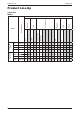
Product Line-Up MWM-J-2011 Product Line-Up Indoor Unit MWM-J 3 CE A ACLAA X X X X X 15J ACLAA X X X X X 20J ACLAA X X X X X 25J ACLAA X X X X X 09JR ACLAA X X X X X 15JR ACLAA X X X X X 20JR ACLAA X X X X X 25JR ACLAA X X X X X Others Grille Marking Air Purification 09J Bio Filter Saranet Filter PCB LGSN Nomenclature G17 HEATPUMP COOLING ONLY MWM Handset Classification
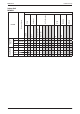
MWM-J-2011 Product Line-Up Indoor Unit M5WM-J CE ACLAA X X X X X 15J ACLAA X X X X X 10JR ACLAA X X X X X 15JR ACLAA X X X X X Others Marking A 10J Bio Filter Saranet Filter Grille Air Purification Handset G17 PCB LGSN HEATPUMP COOLING ONLY M5WM Nomenclature Classification 4
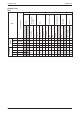
5 Cap Tube 09C ACPOH X X X X 15C ACPOH X X X X 020C ACPOD X X X X 025C ACPOD X X X X 09CR ACPOH X X X X X 15CR ACPOJ X X X X X 020CR ACPOD X X X X X 025CR ACPOD X X X X X Low Ambient Kit Drain Elbow LP HP Contactor Aluminium Fin Blue Fin Gold Fin Others Marking Compressor Safety Devices FIN Refrigerant Control PCB Nomenclature MLC EXV CE COOLING ONLY Rotary HEATPUMP Product Line-Up MWM-J-2011 Outdoor Unit MLC Classification
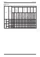
HEATPUMP COOLING ONLY 15CJ 10CRJ 15CRJ ACPGG X X X X ACPOG X X X X ACPGG X X X X ACPOG X X X X ACPOG X X X X ACPOG X X X X Low Ambient Kit Drain Elbow LP HP Contactor Bare Blue Coated Gold Coated EXV CE 10CJ Rotary Cap Tube M5LC Others Marking Compressor Safety Devices FIN Refrigerant Control PCB Nomenclature MWM-J-2011 Product Line-Up Outdoor Unit M5LC Classification X X 6
Features MWM-J-2011 Features Air Filtration with Bio Antibody Filter and Photo-catalytic Deodorizing Titanium Apatite Filter Bio Antibody Filter is effective against various airborne infectious viruses while Titanium Apatite Filter is able to trap microscopic particles as well as break down and decompose odors. The filter can be used for approximately 3 years without replacement if wash about once every six months.
MWM-J-2011 Application Information Application Information Operating Range Ensure the operating temperature is in allowable range. Cooling only Outdoor temp. (°CDB) 46 Standard point 35 ! Caution : 19 The use of your air conditioner outside the range of working temperature and humidity can result in serious failure. Low ambient kit -5 23 14 Indoor temp. (°CWB) Heatpump Cooling Heating Outdoor temp. (°CDB) Outdoor temp.
Application Information MWM-J-2011 Refrigerant Circuit Diagram Model: MWM09J - MLC09C MWM15J - MLC15C M5WM10J - M5LC10CJ M5WM15J - M5LC15CJ 70034 049971 Model: MWM20J - MLC020C 9
MWM-J-2011 Application Information Model: MWM25J - MLC025C Model: MWM09JR - MLC09CR M5WM10JR - M5LC10CRJ M5WM15JR - M5LC15CRJ 70034 023154 10
Application Information MWM-J-2011 Model: MWM15JR - MLC15CR 70034 095236 Model: MWM20JR - MLC020CR 11
MWM-J-2011 Application Information Model: MWM025JR - MLC025CR 12
Application Information MWM-J-2011 Controller G17 1 2 P1 P2 10 9 3 8 MODE 4 SLEEP 7 5 CANCEL SET OFF TIMER 13 ON TIMER SET 14 12 CANCEL 6a 6b 11 15 Operation Guide 1 Transmission Source • The source where the signal will be transmitted. 2 Signal Transmission Indication • Blink to confirm that the last setting has been transmitted to the unit. 3 Temperature Setting • To set the desired room temperature, press the v or V button to increase orde crease the set temperature.
MWM-J-2011 Application Information Installation Guideline Safety Precautions WARNING CAUTION • Installation and maintenance should be performed by qualified persons who are familiar with local code and regulation, and experienced with this type of appliance. • All field wiring must be installed in accordance with the national wiring regulation. • Ensure that the rated voltage of the unit corresponds to that of the name plate before commencing wiring work according to the wiring diagram.
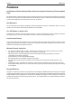
Application Information MWM-J-2011 Installation Diagram Indoor Unit 30mm or more from ceiling Caulk pipe hole gap with putty. Front panel Wrap the insulation pipe with the finishing tape from bottom to top. 50mm or more from walls (on both sides) Air filter Cut thermal insulation pipe to an appropriate length and wrap it with tape, making sure that no gap is left in the insulation pipe's cut line. M4 x 12L Service lid Opening service lid Service lid is opening/closing type.
MWM-J-2011 Application Information Routing of Piping • The refrigerant piping can be routed to the unit in one of 5 directions, by using the cut outs in the unit casing (refer to Figure 1). 3 2 1 4 5 Figure 1 • Carefully bend the pipes to the required position to align with the hole. For right hand and rear side draw out, hold the bottom of the piping and fix direction before shaping it to the desired position (refer to Figure 2).
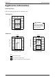
Application Information MWM-J-2011 • Fix the installation plate firmly to the wall, without tilting to left or right. Use a plumb line, if available. Use tape measure as shown. Position the end of a tape measure at 184 Recommended mounting plate retention spots (5 spots in all) 42.2 42.2 42.2 166 45.9 45.9 288 Through the wall hole Ø 65mm 54.5 153.8 263 51.9 181.
MWM-J-2011 Application Information Water Drainage Piping • The indoor drain pipe must be downward gradient for smooth drainage. Avoid situation as shown in figure below. Water Drainage Water Retention Water leaking Water leaking Water leaking End dipped into water Drain Correct Wrong Wrong Wrong Installation of Outdoor Unit Condensed Water Disposal of Outdoor Unit (Heat Pump Unit Only) • There are 2 holes on the base of outdoor unit for condensed water to flow out.
Application Information MWM-J-2011 As condensing temperature rises, evaporating temperature rises and cooling capacity drops. In order to achieve maximum cooling capacity, the location selected for outdoor unit should fulfill the following requirements: • Install the condensing (outdoor) unit in a way such that hot air distributed by the outdoor condensing unit cannot be drawn in again (as in the case of short circuit of hot discharge air). Allow sufficient space for maintenance around the unit.
MWM-J-2011 Application Information Wiring Electrical Connections • Wiring regulations on wire diameters differ from country to country. Please refer to your LOCAL ELECTRICAL CODES for field wiring rules. Be sure that installations comply with the rules and regulations. General Precautions • Ensure that the rated voltage of the unit corresponds to the name plate before carrying out proper wiring according to the wiring diagram. • Provide a power outlet to be used exclusively for each unit.
Application Information MWM-J-2011 Piping Works • Do not use contaminated or damaged copper tubing. Do not remove plastic, rubber plugs and brass nuts from the valves, fittings, tubings and coils until you are ready to connect suction or liquid line into valves or fittings. • If any brazing work is required, ensure that the nitrogen gas is passed through coil and joints while the brazing work is being done. This will eliminate soot formation on the inside walls of the copper tubings.
MWM-J-2011 Application Information Vacuuming and Charging The pre-charged outdoor unit does not need any vacuuming or charging. However once it is connected, the connecting pipe line and the indoor unit need to be vacuumed before releasing the R22/R407C/R410A from the outdoor unit. 1. Open the service port core cap. 2. Connect pressure gauge to the service port. 3. Connect the line to vacuum pump. Open the charging manifold valve and turn the pump on. Vacuum to -0.1 MPa (-760mmHg) or lower.
Application Information MWM-J-2011 Diagram shows typical charging method: (Mclecular-Sieve Type) Note : R22 - Nil R410A - Nil Caution • For R410A, avoid prolong exposure of an opened compressor, or the internal part of refrigerant piping to moist air. The POE oil in the compressor and piping can absorb moisture from air. Overall Checking • Ensure the following, in particular: 1. The unit is mounted solidly and rigid in position. 2. Piping and connections are leak proof after charging. 3.
MWM-J-2011 Application Information Special Precautions When Dealing With Refrigerant R410A Unit (1) What is new refrigerant R410A? R410A is a new HFC refrigerant which does not damage the ozone layer. The working pressure of this new refrigerant is 1.6 times higher than conventional refrigerant (R22), thus proper installation / servicing is essential.
Application Information MWM-J-2011 (d) When charging R410A, ensure that only liquid is being withdrawn from the cylinder or can. This is to ensure that only the original composition of R410A is being delivered into the system. The liquid composition can be different from the vapor composition. Dip-pipe Invert cylinder without dip-pipe Liquid withdrawal (e) Normally, the R410A cylinder or can is being equipped with a dip pipe for liquid withdrawal.
MWM-J-2011 Sound Data Sound Data Sound Pressure Level Speed Model (RPM) MWM09J/JR M5WM10J/JR MWM15J/JR M5WM15J/JR MWM20J/JR MWM25J/JR 1/1 Octave Sound Pressure Level (dB, ref 20μPa) 125 Hz 250 Hz 500 Hz 1k Hz 2k Hz 4k Hz Overall Noise 8k Hz (dBA) Criteria High 30 32 33 29 25 19 9 34 28 Medium 27 29 31 27 22 20 11 32 25 Low 24 26 28 23 19 19 11 29 22 S.
Sound Data MWM-J-2011 MWM09J/JR NC CURVES 60 Sound pressure level (dB,ref20µPa) 50 NC-45 40 NC-40 NC-35 High Fan 30 Medium Fan NC-30 Low Fan NC-25 S.Low Fan 20 NC-20 10 0 125 250 500 1000 2000 4000 8000 Octave-band frequency (Hz) M5WM10J/JR NC CURVES 60 50 Sound pressure level (dB,ref20µPa) NC-45 40 NC-40 NC-35 High Fan 30 NC-30 Medium Fan NC-25 Low Fan 20 NC-20 S.
MWM-J-2011 Sound Data MWM15J/JR, M5WM15J/JR NC CURVES 60 Sound pressure level (dB, ref20µPa) 50 NC45 40 NC-40 30 High Fan NC-35 Medium Fan NC-30 NC-25 Low Fan 20 NC-20 S.Low Fan 10 0 125 250 500 1000 2000 4000 8000 Octave-band frequency (Hz) M5WM20J/JR NC CURVES 60 Sound pressure level (dB,ref20µPa) 50 NC-45 40 NC-40 NC-35 High Fan 30 NC-30 Medium Fan NC-25 Low Fan 20 NC-20 S.
Sound Data MWM-J-2011 MWM25J/JR NC CURVES 60 Sound pressure level (dB,ref20µPa) 50 NC-45 40 NC-40 High Fan NC-35 Medium Fan NC-30 30 NC-25 Low Fan 20 NC-20 S.
MWM-J-2011 Engineering & Physical Data Engineering & Physical Data General Data - Cooling Only (R22) INDOOR UNIT MODEL OUTDOOR UNIT NOMINAL CAPACITY MWM09J MWM15J MLC09C MLC15C Btu/h 8400 12000 W 2460 3520 1176 NOMINAL TOTAL INPUT POWER W 925 NOMINAL RUNNING CURRENT A 4.10 5.40 V/Ph/Hz 220 - 240 / 1 / 50 220 - 240 / 1 / 50 W/W 3.11 3.
Engineering & Physical Data MWM-J-2011 General Data - Cooling Only (R22) MODEL INDOOR UNIT MWM20J MWM25J OUTDOOR UNIT MLC020C MLC025C Btu/h 19500 24000 W 5720 7030 W 1850 2530 NOMINAL CAPACITY NOMINAL TOTAL INPUT POWER NOMINAL RUNNING CURRENT POWER SOURCE EER A 8.21 11.30 V/Ph/Hz 220 - 240 / 1 / 50 220 - 240 / 1 / 50 W/W 3.29 3.
MWM-J-2011 Engineering & Physical Data General Data - Heat pump (R22) MODEL INDOOR UNIT MWM09JR MWM15JR OUTDOOR UNIT MLC09CR MLC15CR Btu/h 8400 11800 NOMINAL COOLING CAPACITY NOMINAL HEATING CAPACITY W 2460 3460 Btu/h 9000 13000 W 2640 3810 NOMINAL TOTAL INPUT POWER (COOLING) W 925 1192 NOMINAL TOTAL INPUT POWER (HEATING) W 750 1064 NOMINAL RUNNING CURRENT (COOLING) A 4.10 5.50 NOMINAL RUNNING CURRENT (HEATING) A 3.40 4.
Engineering & Physical Data MWM-J-2011 General Data - Heat pump (R22) MODEL INDOOR UNIT OUTDOOR UNIT Btu/h NOMINAL COOLING CAPACITY NOMINAL HEATING CAPACITY MWM20JR MWM25JR MLC020CR MLC025CR 19500 24000 W 5720 7030 Btu/h 19500 25000 W 5720 7330 NOMINAL TOTAL INPUT POWER (COOLING) W 1850 2530 NOMINAL TOTAL INPUT POWER (HEATING) W 1750 2465 NOMINAL RUNNING CURRENT (COOLING) A 8.21 11.30 NOMINAL RUNNING CURRENT (HEATING) A 7.73 11.
MWM-J-2011 Engineering & Physical Data General Data - Cooling Only (R410A) MODEL INDOOR UNIT M5WM10J M5WM15J OUTDOOR UNIT M5LC10C M5LC15C Btu/h 9040 10750 NOMINAL CAPACITY W 2650 3150 NOMINAL TOTAL INPUT POWER W 825 1094 NOMINAL RUNNING CURRENT A 3.70 5.10 V/Ph/Hz 220 - 240 / 1 / 50 220 - 240 / 1 / 50 W/W 3.30 3.32 R410A R410A OUTDOOR CAP. TUBE OUTDOOR CAP.
Engineering & Physical Data MWM-J-2011 General Data - Heat pump (R410A) MODEL INDOOR UNIT M5WM10JR M5WM15JR OUTDOOR UNIT M5LC10CR M5LC15CR 9040 10750 Btu/h NOMINAL COOLING CAPACITY NOMINAL HEATING CAPACITY W 2650 3150 Btu/h 9550 11530 W 2800 3380 NOMINAL TOTAL INPUT POWER (COOLING) W 825 1094 NOMINAL TOTAL INPUT POWER (HEATING) W 775 988 NOMINAL RUNNING CURRENT (COOLING) A 3.70 5.10 NOMINAL RUNNING CURRENT (HEATING) A 3.20 4.
MWM-J-2011 Engineering & Physical Data Component Data - Cooling Only (R22) MODEL INDOOR UNIT MWM09J MWM15J OUTDOOR UNIT MLC09C MLC15C CROSS FLOW FAN CROSS FLOW FAN TYPE INDOOR FAN QUANTITY 1 1 MATERIAL GLASS REINFORCED ACRYL STYRENE RESIN GLASS REINFORCED ACRYL STYRENE RESIN DIRECT DIRECT DRIVE DIAMETER mm/in 92 / 3.6 92 / 3.6 LENGTH mm/in 607 / 23.9 607 / 23.
Engineering & Physical Data MWM-J-2011 Component Data - Cooling Only (R22) MODEL INDOOR UNIT MWM20J OUTDOOR UNIT MLC020C MLC025C CROSS FLOW FAN CROSS FLOW FAN QUANTITY 1 1 MATERIAL GLASS REINFORCED ACRYL STYRENE RESIN GLASS REINFORCED ACRYL STYRENE RESIN TYPE INDOOR FAN DRIVE DIAMETER mm/in LENGTH mm/in TYPE INDOOR FAN MOTOR QUANTITY INDEX OF PROTECTION (IP) 867 / 34.
MWM-J-2011 Engineering & Physical Data Component Data - Heat Pump (R22) MODEL INDOOR UNIT MWM09JR OUTDOOR UNIT MLC09CR MLC15CR CROSS FLOW FAN CROSS FLOW FAN TYPE QUANTITY 1 1 MATERIAL GLASS REINFORCED ACRYL STYRENE RESIN GLASS REINFORCED ACRYL STYRENE RESIN DIRECT DIRECT INDOOR FAN DRIVE DIAMETER mm/in 92 / 3.6 92 / 3.6 LENGTH mm/in 607 / 23.9 607 / 23.
Engineering & Physical Data MWM-J-2011 Component Data - Heat Pump (R22) MODEL INDOOR UNIT MWM20JR OUTDOOR UNIT MLC020CR MLC025CR CROSS FLOW FAN CROSS FLOW FAN QUANTITY 1 1 MATERIAL GLASS REINFORCED ACRYL STYRENE RESIN GLASS REINFORCED ACRYL STYRENE RESIN TYPE INDOOR FAN DRIVE DIRECT DIRECT DIAMETER mm/in 102 / 4.02 102 / 4.02 LENGTH mm/in 867 / 34.13 867 / 34.
MWM-J-2011 Engineering & Physical Data Component Data - Cooling Only (R410A) MODEL INDOOR UNIT M5WM10J OUTDOOR UNIT M5LC10C M5LC15C CROSS FLOW FAN CROSS FLOW FAN TYPE QUANTITY 1 1 MATERIAL GLASS REINFORCED ACRYL STYRENE RESIN GLASS REINFORCED ACRYL STYRENE RESIN DIRECT DIRECT INDOOR FAN DRIVE DIAMETER mm/in 92 / 3.6 92 / 3.6 LENGTH mm/in 607 / 23.9 607 / 23.
Engineering & Physical Data MWM-J-2011 Component Data - Heat Pump (R410A) MODEL INDOOR UNIT M5WM10JR OUTDOOR UNIT M5LC10CR M5LC15CR CROSS FLOW FAN CROSS FLOW FAN TYPE QUANTITY 1 1 MATERIAL GLASS REINFORCED ACRYL STYRENE RESIN GLASS REINFORCED ACRYL STYRENE RESIN DIRECT DIRECT INDOOR FAN DRIVE DIAMETER mm/in 92 / 3.6 92 / 3.6 LENGTH mm/in 607 / 23.9 607 / 23.
MWM-J-2011 Performance Data Performance Data Calculation Steps Interpolation method can be used to get the total capacity, TC and sensible capacity, SC and power input, PI at those temperatures which are not stated out in the table. Extrapolation method are not allowed to be used to get the TC, SC and PI Example: Model: MWM09J - MLC09C Indoor Condition: 25°C DB, 17°C WB Outdoor Condition: 37°C DB Fan speed: High Solution: Overall Based on the Performance table: 1.
Performance Data MWM-J-2011 Details: 1st Step: To obtain the Total capacity, Sensible capacity and Power input for (a) Indoor Condition: 25°C DB, 16°C WB Outdoor Condition: 35°C DB Outdoor DB, ˚C Indoor DB˚C Indoor WB˚C 35 24 16 25 ........................................... 27 Total capacity, TC Interpolation Method: ⇒ 25º C – 24º C 27º C – 24º C = x1 – 10.85kW 11.03kW – 10.85kW ⇒ x1 = 10.91kW Sensible capacity, SHC Interpolation Method: ⇒ 25º C – 24º C 27º C – 24º C = y1 – 10.39kW 11.
MWM-J-2011 Performance Data (b) Indoor Condition: 25°C DB, 16°C WB Outdoor Condition: 40°C DB Outdoor DB, ˚C Indoor DB˚C Indoor WB˚C 40 24 16 25 ........................................... 27 TC (kW) SHC (kW) PI (kW) 10.42 10.23 x2 y2 4.36 z2 10.66 10.66 4.38 Total capacity, TC Interpolation Method: ⇒ 25º C – 24º C 27º C – 24º C = x2 – 10.42kW 11.66kW – 10.42kW ⇒ x1 = 10.50kW Sensible capacity, SHC Interpolation Method: ⇒ 25º C – 24º C 27º C – 24º C = y2 – 10.23kW 10.66kW – 10.
Performance Data MWM-J-2011 2nd Step: To obtain the Total capacity, Sensible capacity and Power input for (a) Indoor Condition: 25°C DB, 17°C WB Outdoor Condition: 35°C DB Outdoor DB, ˚C Indoor DB˚C Indoor WB˚C 35 17 25 ........................................... 19 Total capacity, TC Interpolation Method: ⇒ 17º C – 16º C 19º C – 16º C = x5 – 10.91kW 11.65kW – 10.91kW ⇒ x5 = 11.16kW Sensible capacity, SHC Interpolation Method: ⇒ 17º C – 16º C 19º C – 16º C = y5 – 10.60kW 8.94kW – 10.
MWM-J-2011 Performance Data (b) Indoor Condition: 25°C DB, 17°C WB Outdoor Condition: 40°C DB Outdoor DB, ˚C Indoor DB˚C Indoor WB˚C 40 17 25 ........................................... 18 PI (kW) ........ 16 SHC (kW) ........ TC (kW) 10.50 x6 10.37 y6 4.37 z6 11.36 9.03 4.43 Total capacity, TC Interpolation Method: ⇒ 17º C – 16º C 19º C – 16º C = x6 – 10.50kW 11.36kW – 10.50kW ⇒ x6 = 10.79kW Sensible capacity, SHC Interpolation Method: ⇒ 17º C – 16º C 19º C – 16º C = y6 – 10.
Performance Data MWM-J-2011 3rd Step: To obtain the Total capacity and Sensible capacity for (a) Indoor Condition: 25°C DB, 17°C WB Outdoor Condition: 37°C DB Outdoor DB, ˚C Indoor DB˚C Indoor WB˚C 23 15 35 TC (kW) ...................... PI (kW) TC (kW) SHC (kW) PI (kW) TC (kW) SHC (kW) PI (kW) 11.16 10.05 4.03 x y z 10.79 9.92 4.39 Interpolation Method: 37º C – 35º C 40º C – 35º C = x – 11.16kW 10.79kW – 11.16kW ⇒ x = 11.
MWM-J-2011 Performance Data Cooling Only (R22) Model: MWM09J - MLC09C Cooling Mode Outdoor temperature AFR EWB (CFM) EDB 19°C TC 16°C 222 19°C 22°C 16°C 279 19°C 22°C 16°C 335 19°C 22°C SHC 25°C PI TC SHC 30°C PI TC SHC 35°C PI TC SHC 40°C PI TC SHC 46°C PI TC SHC PI 21°C 2.32 1.82 0.70 2.24 1.77 0.76 2.16 1.72 0.82 2.07 1.67 0.89 1.90 1.56 0.97 1.75 1.46 1.07 24°C 2.32 2.17 0.70 2.24 2.13 0.76 2.16 2.08 0.82 2.07 2.02 0.89 1.90 1.89 0.97 1.76 1.76 1.07 27°C 2.34 2.
Performance Data MWM-J-2011 Model: MWM15J - MLC15C Cooling Mode Outdoor temperature AFR EWB (CFM) EDB 19°C TC 16°C 240 19°C 22°C 16°C 293 19°C 22°C 16°C 346 19°C 22°C SHC 25°C PI TC SHC 30°C PI TC SHC 35°C PI TC PI TC SHC 46°C PI TC SHC PI 21°C 3.32 2.38 0.89 3.20 2.31 0.97 3.08 2.25 1.05 2.96 2.19 1.13 2.71 2.04 1.23 2.51 1.92 1.36 24°C 3.32 2.85 0.89 3.20 2.78 0.97 3.08 2.72 1.05 2.96 2.65 1.14 2.72 2.47 1.23 2.52 2.33 1.36 27°C 3.35 3.23 0.90 3.23 3.15 0.97 3.12 3.
MWM-J-2011 Performance Data Model: MWM20J - MLC020C Cooling Mode Outdoor temperature AFR EWB (CFM) EDB 19°C TC 16°C 424 19°C 22°C 16°C 478 19°C 22°C 16°C 536 19°C 22°C SHC 25°C PI TC SHC 30°C PI TC SHC 35°C PI TC SHC 40°C PI TC SHC 46°C PI TC SHC PI 21°C 5.25 3.57 1.41 5.07 3.47 1.52 4.88 3.38 1.65 4.68 3.28 1.79 4.30 3.06 1.94 3.97 2.87 2.14 24°C 5.26 4.27 1.41 5.07 4.17 1.52 4.88 4.08 1.65 4.69 3.98 1.79 4.31 3.71 1.94 3.98 3.50 2.14 27°C 5.30 4.84 1.41 5.12 4.73 1.
Performance Data MWM-J-2011 Model: MWM25J - MLC025C Cooling Mode Outdoor temperature AFR EWB (CFM) EDB 19°C TC 16°C 474 19°C 22°C 16°C 537 19°C 22°C 16°C 616 19°C 22°C SHC 25°C PI TC SHC 30°C PI TC SHC 35°C PI TC PI TC SHC 46°C PI TC SHC PI 21°C 6.49 4.59 1.88 6.26 4.47 2.04 6.03 4.35 2.21 5.79 4.23 2.39 5.32 3.94 2.60 4.91 3.70 2.86 24°C 6.50 5.50 1.88 6.27 5.38 2.04 6.04 5.25 2.21 5.80 5.12 2.39 5.33 4.78 2.60 4.93 4.51 2.86 27°C 6.55 6.24 1.89 6.34 6.10 2.04 6.11 5.
MWM-J-2011 Performance Data Heat Pump (R22) Model: MWM09JR - MLC09CR Cooling Mode Outdoor temperature AFR EWB (CFM) EDB 19°C TC 16°C 222 19°C 22°C 16°C 279 19°C 22°C 16°C 335 19°C 22°C SHC 25°C PI TC SHC 30°C PI TC SHC 35°C PI TC SHC 40°C PI TC SHC 46°C PI TC SHC PI 21°C 2.32 1.82 0.70 2.24 1.77 0.76 2.16 1.72 0.82 2.07 1.67 0.89 1.90 1.56 0.97 1.75 1.46 1.07 24°C 2.32 2.17 0.70 2.24 2.13 0.76 2.16 2.08 0.82 2.07 2.02 0.89 1.90 1.89 0.97 1.76 1.76 1.07 27°C 2.34 2.
Performance Data MWM-J-2011 Model: MWM09JR - MLC09CR Heating Mode Outdoor WB°C ID DB°C -9 -6 -5 6 12 15 18 TC(kW) SC(kW) TC(kW) SC(kW) TC(kW) SC(kW) TC(kW) SC(kW) TC(kW) SC(kW) TC(kW) SC(kW) TC(kW) SC(kW) 15 1.169 1.169 1.441 1.441 1.532 1.532 2.528 2.528 3.071 3.071 3.343 3.343 3.615 3.615 17 1.145 1.145 1.414 1.414 1.503 1.503 2.523 2.523 2.988 2.988 3.250 3.250 3.512 3.512 19 1.122 1.122 1.386 1.386 1.474 1.474 2.517 2.517 2.904 2.904 3.157 3.157 3.
MWM-J-2011 Performance Data Model: MWM15JR - MLC15CR Cooling Mode Outdoor temperature AFR EWB (CFM) EDB 19°C TC 16°C 240 19°C 22°C 16°C 293 19°C 22°C 16°C 346 19°C 22°C SHC 25°C PI TC SHC 30°C PI TC SHC 35°C PI TC SHC 40°C PI TC SHC 46°C PI TC SHC PI 21°C 3.26 2.34 0.91 3.14 2.28 0.98 3.03 2.21 1.06 2.91 2.15 1.15 2.67 2.00 1.25 2.46 1.88 1.38 24°C 3.26 2.80 0.91 3.15 2.73 0.98 3.03 2.67 1.06 2.91 2.60 1.15 2.67 2.43 1.25 2.47 2.29 1.38 27°C 3.29 3.17 0.91 3.18 3.10 0.
Performance Data MWM-J-2011 Model: MWM15JR - MLC15CR Heating Mode Outdoor WB°C ID DB°C -9 -6 -5 6 12 15 18 TC(kW) SC(kW) TC(kW) SC(kW) TC(kW) SC(kW) TC(kW) SC(kW) TC(kW) SC(kW) TC(kW) SC(kW) TC(kW) SC(kW) 15 1.684 1.684 2.074 2.074 2.204 2.204 3.634 3.634 4.414 4.414 4.804 4.804 5.194 5.194 17 1.650 1.650 2.034 2.034 2.162 2.162 3.632 3.632 4.294 4.294 4.670 4.670 5.046 5.046 19 1.616 1.616 1.995 1.995 2.121 2.121 3.630 3.630 4.174 4.174 4.536 4.536 4.
MWM-J-2011 Performance Data Model: MWM20JR - MLC020CR Cooling Mode Outdoor temperature AFR EWB (CFM) EDB 19°C TC 16°C 424 19°C 22°C 16°C 478 19°C 22°C 16°C 536 19°C 22°C SHC 25°C PI TC SHC 30°C PI TC SHC 35°C PI TC SHC 40°C PI TC SHC 46°C PI TC SHC PI 21°C 5.39 3.66 1.41 5.20 3.57 1.52 5.01 3.47 1.65 4.80 3.37 1.79 4.41 3.14 1.94 4.07 2.95 2.14 24°C 5.40 4.38 1.41 5.20 4.28 1.52 5.01 4.18 1.65 4.81 4.08 1.79 4.42 3.81 1.94 4.09 3.60 2.14 27°C 5.44 4.97 1.41 5.26 4.
Performance Data MWM-J-2011 Model: MWM20JR - MLC020CR Heating Mode Outdoor WB°C ID DB°C -9 -6 -5 6 12 15 18 TC(kW) SC(kW) TC(kW) SC(kW) TC(kW) SC(kW) TC(kW) SC(kW) TC(kW) SC(kW) TC(kW) SC(kW) TC(kW) SC(kW) 15 2.446 2.446 17 2.381 2.381 19 2.316 2.316 21 2.252 2.252 23 2.250 2.250 25 2.249 2.249 27 2.248 2.248 3.074 3.074 3.284 3.284 5.590 5.590 6.847 6.847 7.476 7.476 8.105 8.105 3.011 3.011 3.221 3.221 5.541 5.541 6.661 6.661 7.268 7.268 7.874 7.874 2.
MWM-J-2011 Performance Data Model: MWM25JR - MLC025CR Cooling Mode Outdoor temperature AFR EWB (CFM) EDB 19°C TC 16°C 474 19°C 22°C 16°C 537 19°C 22°C 16°C 616 19°C 22°C SHC 25°C PI TC SHC 30°C PI TC SHC 35°C PI TC SHC 40°C PI TC SHC 46°C PI TC SHC PI 21°C 6.49 4.59 1.88 6.26 4.47 2.04 6.03 4.35 2.21 5.79 4.23 2.39 5.32 3.94 2.60 4.91 3.70 2.86 24°C 6.50 5.50 1.88 6.27 5.38 2.04 6.04 5.25 2.21 5.80 5.12 2.39 5.33 4.78 2.60 4.93 4.51 2.86 27°C 6.55 6.24 1.89 6.34 6.
Performance Data MWM-J-2011 Model: MWM25JR - MLC025CR Heating Mode Outdoor WB°C ID DB°C -9 -6 -5 6 12 15 18 TC(kW) SC(kW) TC(kW) SC(kW) TC(kW) SC(kW) TC(kW) SC(kW) TC(kW) SC(kW) TC(kW) SC(kW) TC(kW) SC(kW) 15 3.926 3.926 4.540 4.540 4.745 4.745 6.995 6.995 8.223 8.223 8.836 8.836 9.450 9.450 17 3.920 3.920 4.477 4.477 4.662 4.662 6.989 6.989 8.003 8.003 8.592 8.592 9.182 9.182 19 3.914 3.914 4.414 4.414 4.580 4.580 6.984 6.984 7.783 7.783 8.348 8.348 8.
MWM-J-2011 Performance Data Cooling Only (R410A) Model: M5WM10J - M5LC10CJ Cooling Mode Outdoor temperature AFR EWB (CFM) EDB 19°C TC 16°C 222 19°C 22°C 16°C 279 19°C 22°C 16°C 335 19°C 22°C SHC 25°C PI TC SHC 30°C PI TC SHC 35°C PI TC SHC 40°C PI TC SHC 46°C PI TC SHC PI 21°C 2.50 1.93 0.63 2.41 1.88 0.68 2.32 1.83 0.73 2.23 1.78 0.80 2.04 1.65 0.86 1.89 1.56 0.95 24°C 2.50 2.31 0.63 2.41 2.26 0.68 2.32 2.21 0.73 2.23 2.15 0.80 2.05 2.01 0.86 1.90 1.90 0.95 27°C 2.
Performance Data MWM-J-2011 Model: M5WM15J - M5LC15CJ Cooling Mode Outdoor temperature AFR EWB (CFM) EDB 19°C TC 16°C 240 19°C 22°C 16°C 293 19°C 22°C 16°C 346 19°C 22°C SHC 25°C PI TC SHC 30°C PI TC SHC 35°C PI TC PI TC SHC 46°C PI TC SHC PI 21°C 2.97 2.18 0.83 2.86 2.13 0.90 2.76 2.07 0.97 2.65 2.01 1.06 2.43 1.87 1.15 2.24 1.76 1.26 24°C 2.97 2.62 0.83 2.87 2.56 0.90 2.76 2.50 0.97 2.65 2.43 1.06 2.44 2.27 1.15 2.25 2.15 1.26 27°C 3.00 2.97 0.83 2.90 2.90 0.90 2.
MWM-J-2011 Performance Data Heat Pump (R410A) Model: M5WM10JR - M5LC10CRJ Cooling Mode Outdoor temperature AFR EWB (CFM) EDB 19°C TC 16°C 222 19°C 22°C 16°C 279 19°C 22°C 16°C 335 19°C 22°C SHC 25°C PI TC SHC 30°C PI TC SHC 35°C PI TC SHC 40°C PI TC SHC 46°C PI TC SHC PI 21°C 2.50 1.93 0.61 2.41 1.88 0.66 2.32 1.83 0.71 2.23 1.78 0.77 2.04 1.65 0.84 1.89 1.56 0.93 24°C 2.50 2.31 0.61 2.41 2.26 0.66 2.32 2.21 0.71 2.23 2.15 0.77 2.05 2.01 0.84 1.90 1.90 0.93 27°C 2.
Performance Data MWM-J-2011 Model: M5WM10JR - M5LC10CRJ Heating Mode Outdoor WB°C ID DB°C -9 -6 -5 6 12 15 18 TC(kW) SC(kW) TC(kW) SC(kW) TC(kW) SC(kW) TC(kW) SC(kW) TC(kW) SC(kW) TC(kW) SC(kW) TC(kW) SC(kW) 15 1.692 1.692 1.915 1.915 1.989 1.989 2.807 2.807 3.253 3.253 3.476 3.476 3.700 3.700 17 1.648 1.648 1.850 1.850 1.944 1.944 2.804 2.804 3.201 3.201 3.423 3.423 3.645 3.645 19 1.603 1.603 1.785 1.785 1.898 1.898 2.801 2.801 3.149 3.149 3.370 3.370 3.
MWM-J-2011 Performance Data Heat Pump (R410A) Model: M5WM15JR - M5LC15CRJ Cooling Mode Outdoor temperature AFR EWB (CFM) EDB 19°C TC 16°C 240 19°C 22°C 16°C 293 19°C 22°C 16°C 346 19°C 22°C SHC 25°C PI TC SHC 30°C PI TC SHC 35°C PI TC SHC 40°C PI TC SHC 46°C PI TC SHC PI 21°C 2.97 2.18 0.83 2.86 2.13 0.90 2.76 2.07 0.97 2.65 2.01 1.06 2.43 1.87 1.15 2.24 1.76 1.26 24°C 2.97 2.62 0.83 2.87 2.56 0.90 2.76 2.50 0.97 2.65 2.43 1.06 2.44 2.27 1.15 2.25 2.15 1.26 27°C 3.
Performance Data MWM-J-2011 Model: M5WM15JR - M5LC15CRJ Heating Mode Outdoor WB°C ID DB°C -9 -6 -5 6 12 15 18 TC(kW) SC(kW) TC(kW) SC(kW) TC(kW) SC(kW) TC(kW) SC(kW) TC(kW) SC(kW) TC(kW) SC(kW) TC(kW) SC(kW) 15 2.043 2.043 2.312 2.312 2.402 2.402 3.389 3.389 3.928 3.928 4.197 4.197 4.467 4.467 17 1.989 1.989 2.255 2.255 2.347 2.347 3.385 3.385 3.869 3.869 4.137 4.137 4.406 4.406 19 1.936 1.936 2.197 2.197 2.293 2.293 3.381 3.381 3.810 3.810 4.078 4.078 4.
MWM-J-2011 Outline and Dimension Outline and Dimension Indoor Unit Model: MWM09/15J/JR, M5WM10/15J/JR 800 206 288 288 TOP VIEW SIDE VIEW LOUVER FRONT VIEW 50123456789 Note: Dimension in mm Outdoor Unit Model: MLC09/15C/CR, M5LC10/15C/CR K L N 30 (1.2) C M N L C H F G 19 ( 0.7) 80 65 (3.1) (2.6) B E 3 (0 .1 ) A D O Dimension 10 / 15C / CR I J A B C D E F G H I J K L M N O 700 521 250 485 175 36 95 93 86 68 441 130 111 15 18 (27.5) (20.5) (9.
Outline and Dimension MWM-J-2011 Indoor Unit Model: MWM20/25J/JR 1065 224 310 310 TOP VIEW SIDE VIEW LOUVER FRONT VIEW Note: Dimension in mm Outdoor Unit Model: MLC020/025C/CR For M5LC / MLC025C/CR Note : Dimension in mm MODEL A B C D E F G H I J K L M N O P Q R S T MLC020C/CR 855 628 328 508 181 44 93 149 101 113 603 126 164 17 49 32 3 23 73 75 MLC025C/CR 855 730 328 513 182 44 93 149 101 113 603 126 164 17 47 32 3 23 73 75 Note: Di
MWM-J-2011 Electrical Data Electrical Data Electrical Data - Cooling Only (R22) MODEL INDOOR UNIT MLC09C MLC15C INSULATION GRADE CLASS E CLASS E V/Ph/Hz 220 - 240 / 1/ 50 220 - 240 / 1/ 50 W 31 40 RATED RUNNING CURRENT A 0.18 0.20 MOTOR OUTPUT W 18 18 RATED INPUT POWER POLES INSULATION GRADE POWER SOURCE OUTDOOR MOTOR V/Ph/Hz 4 4 CLASS B CLASS B 220 - 240 / 1/ 50 220 - 240 / 1/ 50 RATED INPUT POWER W 45 59 RATED RUNNING CURRENT A 0.20 0.
Electrical Data MWM-J-2011 Electrical Data - Cooling Only (R22) MODEL INDOOR UNIT MWM20J MWM25J OUTDOOR UNIT MLC020C MLC025C INSULATION GRADE CLASS E CLASS E V/Ph/Hz 220 - 240 / 1 / 50 220 - 240 / 1 / 50 W 60 72 RATED RUNNING CURRENT A 0.27 0.34 MOTOR OUTPUT W 26 30 4 4 POWER SOURCE INDOOR MOTOR RATED INPUT POWER POLES INSULATION GRADE POWER SOURCE OUTDOOR MOTOR V/Ph/Hz CLASS B 220 - 240 / 1 / 50 RATED INPUT POWER W 120 124 RATED RUNNING CURRENT A 0.53 0.
MWM-J-2011 Electrical Data Electrical Data - Cooling Only (R410A) MODEL INDOOR UNIT M5WM10J M5WM15J OUTDOOR UNIT M5LC10C M5LC15C INSULATION GRADE CLASS E CLASS E V/Ph/Hz 220 - 240 / 1/ 50 220 - 240 / 1/ 50 W 32 40 RATED RUNNING CURRENT A 0.17 0.20 MOTOR OUTPUT W 18 18 POWER SOURCE INDOOR MOTOR RATED INPUT POWER POLES INSULATION GRADE POWER SOURCE OUTDOOR MOTOR V/Ph/Hz 4 CLASS B 220 - 240 / 1/ 50 220 - 240 / 1/ 50 RATED INPUT POWER W 52 59 RATED RUNNING CURRENT A 0.
Wiring Diagram MWM-J-2011 Wiring Diagram Cooling Only Indoor Unit Model: MWM09/15J M5WM10/15J Outdoor Unit Model: MLC09/15CJ M5LC10/15CJ 70034 101945 69
MWM-J-2011 Wiring Diagram Cooling Only Indoor Unit Model: MWM20/25J Outdoor Unit Model: MLC020/025C 70034 108883 70
Wiring Diagram MWM-J-2011 Heat Pump Indoor Unit Model: MWM09/15JR M5WM10/15JR Outdoor Unit Model: MLC09/15CRJ M5LC10/15CRJ 70034 101944 71
MWM-J-2011 Wiring Diagram Heat Pump Indoor Unit Model: MWM20/25JR Outdoor Unit Model: MLC020/025CR 70034 108882 72
Service and Maintenance MWM-J-2011 Service and Maintenance Warning • Disconnect from main supply before servicing the air conditioner. • The unit is designed to give long life operation with minimum maintenance required. However, it should be regularly checked and the following items should be given due attention. Components Maintenance Procedures Period Air Filter (Indoor Unit) 1.
MWM-J-2011 Service and Maintenance Pre Start Up Maintenance (After Extended Shutdown) • • • • • • • Inspect thoroughly and clean indoor and outdoor units. Clean or replace air filters. Clean condensates drain line. Clean clogged indoor and outdoor coils. Check fan imbalance before operation. Tighten all wiring connections and panels. Check for refrigerant leakage. Outdoor Models The design of the M5LC outdoor series allows servicing to be carried out easily.
Troubleshooting MWM-J-2011 Troubleshooting Error Code / Fault Condition When a malfunction of the air conditioner unit is detected, immediately switch off the main power supply before proceeding with the following troubleshooting procedures. The following are common fault conditions and simple troubleshooting tips. If any other fault conditions which are not listed occur, contact your nearest local dealer. DO NOT attempt to troubleshoot the unit by yourself.
MWM-J-2011 Troubleshooting Diagnostic Guidelines By means of pressure readings: High side Low side High side Low side High side Low side High side Low side High side Low side • • • • Probable cause Too high A little high Normal Too low Circuit Pressure A little low Data • 1. 2. 3. 4. Overcharged with refrigerant. Non-condensable gases in refrigerant circuit (e.g. air) Obstructed air-intake / discharge. Hot air short circuiting in outdoor unit. 1.
Troubleshooting MWM-J-2011 By means of diagnostic flow chart: Generally, there are two kinds of problems, i.e. starting failure and insufficient cooling/heating. “Starting failure” is caused by electrical defect while improper application or defects in refrigerant circuit causes “Insufficient cooling / heating”.
MWM-J-2011 1 Troubleshooting 2 Condenser fan contactor Faulty Coil burnt Contact faulty Blown Fan motor faulty Other electrical component faulty Evaporator contactor Faulty Coil burnt Contact faulty Open compressor windings Incorrect wiring Change the contactor Change the contacts Repair or replace the motor contactor Repair or change if necessary Change the contactor Change the contacts Change the compressor Correct the wiring The most common causes of air conditioner failure to “start” are
Troubleshooting MWM-J-2011 ii ) Diagnosis of Refrigerant Circuit / Application There might be some causes where the unit starts running but does not perform satisfactorily, i.e. insufficient cooling. Judgement could be made by measuring temperature difference of indoor unit’s intake and discharge air as well as running current.
MWM-J-2011 Troubleshooting Insufficient heating Air circulation Restricted Indoor/outdoor coil dirty (clogged) Indoor air filter dirty Fan motor malfunction Obstruction at air inlet /outlet of indoor / outdoor unit High heating load Refrigerant circuit Windows / doors wide open Refrigerant short charge or refrigerant leakage Restriction e.g. at strainer, capillary, filter dryer, etc.
Troubleshooting MWM-J-2011 Indicator Lights IR Signal Receiver When an infra red remote control operating signal has been transmitted, the signal receiver on the indoor unit will respond as below to confirm acceptance of the signal transmission. ON to OFF 1 Long Beep OFF to ON Pump down/Cool force on 2 Short Beep Others 1 Short Beep Cooling Unit / Heat Pump Unit The table below shows the LED indicator lights for the air conditioner unit under normal operation and fault conditions.
MWM-J-2011 Troubleshooting LED Indoor Lights: Normal Operation and Fault Conditions for Cooling / Heat Pump Unit 1 COOL/HEAT (GREEN/RED) Error Code Normal Operation / Fault Indication Green Red Red Green 1 time 3 times 2 times 1 time 6 times ON - Heat mode - Auto mode in Heating operation - Auto mode in Cooling operation - Time on - Sleep mode on - Fan mode on - Dry mode on Room air sensor contact loose / short Blink E3 Outdoor coil sensor open Blink E2 Indoor coil sensor open
Exploded View and Part List MWM-J-2011 Exploded View and Part List INDOOR UNIT MODEL: MWM09/15J/JR, M5WM10/15J/JR 16 13 15 8 14 11 12 18 4 10 3 9 1 17 7 22 5 6 2 21 20 19 70024102581 Note: All exploded view and part list are subjected to change by the manufacturer without prior notice 83
MWM-J-2011 Exploded View and Part List INDOOR UNIT MODEL: MWM09/15J/JR, M5WM10/15J/JR No Description No Description 1 Assy. Front Grille 13 Right Side Panel 2 Panel, McQuay 14 Cover, Drip Proof 3 Disch. Grille Hor.Blade Assy. 15 Clip, Coil Sensor 4 Assy. Bottom Frame 16 Assy. Heat Exchanger 5 Assy. Control Box 17 Assy. Drain Hose 6 Assy. Service Cover 18 Fan Bearing Vibration Absorber 7 Assy.
Exploded View and Part List MWM-J-2011 INDOOR UNIT MODEL: MWM20/25J/JR No Description No Description 1 Assy, Chassis 11 Assy, PCB (with Lamp Cover) 2 Motor 12 Control Box Cover 3 Blower 13 Service Cover 4 Fan Bush 14 Assy, Mounting Plate 5 Motor Cover 15 Assy, Front Cover 6 Assy, Indoor Coil 16 Front Cover 7 Assy, Air Discharge Housing 17 Intake Grill 8 Assy, Louver 18 Filter 9 Hose 19 Handset Wireless 10 Assy, Control Box Note: All exploded view and part list ar
MWM-J-2011 Exploded View and Part List OUTDOOR UNIT MODEL: MLC09C 70024056770 No Description No Description 1 Assy. Base Pan 13 Assy. Control Panel 2 Assy. Outdoor Coil 14 Assy. Valve Cover 3 Valve Bracket 15 Assy. Front Grille 4 Compressor 16 Plastic Handle 5 Assy. Partition 17 Rubber Grommet 6 Assy. Cap Tube 18 7 Bracket, Fan Motor Assy. Flare Valve 2 Ways 1/4” 8 Fan Motor 19 Assy. Flare Valve 3 Ways 3/8” 9 Fan Blade 10 Left Panel 11 Right Panel 12 Assy.
Exploded View and Part List MWM-J-2011 OUTDOOR UNIT MODEL: MLC15C, M5LC10/15C 70024056771 No Description No Description 1 Assy. Base Pan 13 Assy. Control Panel 2 Assy. Outdoor Coil 14 Assy. Valve Cover 3 Valve Bracket 15 Assy. Front Grille 4 Compressor 16 Plastic Handle 5 Assy. Partition 17 Rubber Grommet 6 Assy. Cap Tube 18 Assy. Flare Valve 2 Ways 1/4” 7 Bracket, Fan Motor 19 Assy.
MWM-J-2011 Exploded View and Part List OUTDOOR UNIT MODEL: MLC09CR 70024061683 Note: All exploded view and part list are subjected to change by the manufacturer without prior notice 88
Exploded View and Part List MWM-J-2011 OUTDOOR UNIT MODEL: MLC09CR No Description No Description 1 Assy. Base Pan 14 Assy. Control Panel 2 Assy. Outdoor Coil 15 Assy. Valve Cover 3 Valve Bracket 16 Assy. Front Grille 4 Compressor 17 Plastic Handle 5 Assy. Partition 18 Rubber Grommet 6 Assy. 4 Way Valve 19 7 Assy. Cap Tube Assy. Flare Valve 2 Ways 1/4” 8 Bracket, Fan Motor 20 Assy.
MWM-J-2011 Exploded View and Part List OUTDOOR UNIT MODEL: MLC15CR, M5LC10/15CR 70024061687 No Description No Description 1 Assy. Base Pan 14 Assy. Control Panel 2 Assy. Outdoor Coil 15 Assy. Valve Cover 3 Valve Bracket 16 Assy. Front Grille 4 Compressor 17 Plastic Handle 5 Assy. Partition 18 Rubber Grommet 6 Assy. 4 Way Valve 19 Assy. Flare Valve 2 Ways 1/4” 7 Assy. Cap Tube 20 Assy.
Exploded View and Part List MWM-J-2011 OUTDOOR UNIT MODEL: MLC020C/CR Note: All exploded view and part list are subjected to change by the manufacturer without prior notice 91
MWM-J-2011 Exploded View and Part List OUTDOOR UNIT MODEL: MLC020C No Description No Description 1 Assy. Base Pan 13 Top Panel 2 Assy. Outdoor Coil 14 Assy. Front Grille 3 Bracket, Fan Motor 15 Plastic Handle 4 Fan Motor 16 Assy. Valve Cover 5 Fan Propeller 17 Assy. Cap Tube 6 Assy. Valve Bracket 18 Partition 7 Back Panel, Right 8 Compressor Capacitor, Fan Motor 9 Front Panel, Left Capacitor, Compressor 10 Service Panel Assy.
Exploded View and Part List MWM-J-2011 OUTDOOR UNIT MODEL: MLC025C/CR Note: All exploded view and part list are subjected to change by the manufacturer without prior notice 93
MWM-J-2011 Exploded View and Part List OUTDOOR UNIT MODEL: MLC025C No Description No Description 1 Assy. Base Pan 13 Top Panel 2 Assy. Outdoor Coil 14 Assy. Front Grille 3 Bracket, Fan Motor 15 Plastic Handle 4 Fan Motor 16 Assy. Valve Cover 5 Fan Propeller 17 Assy. Cap Tube 6 Assy. Valve Bracket 18 Partition 7 Back Panel, Right 8 Compressor Capacitor, Fan Motor Assy. Compressor Capacitor, Compressor 9 Front Panel, Left Assy.
Products manufactured in an ISO certified facility. This document contains the most current product information as of this printing. For the most up-to-date product information, please go to www.mcquayup.com © 2011 McQuay Internationalwww.mcquayup.