Catalog MWM-J _ (ii) Supercedes: MWM-J-2010 Wall Mounted Split Systems Models: MWM09J/JR MWM15J/JR MWM20J/JR MWM25J/JR M5WM10J/JR M5WM15J/JR M5WM20J/JR M5WM25J/JR
MWM-J_(ii) Table of Contents Table of Contents Supercedes : MWM-J-2010 Nomenclature......................................................................................................................1 Indoor Unit .....................................................................................................................1 Outdoor Unit ..................................................................................................................1 Product Line-Up..............................
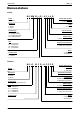
Nomenclature MWM-J_(ii) Nomenclature Indoor M 5 WM 2 0 J R – A C L A B Brand M: McQuay Product Specification Variation B : Second Issue Refrigerant “ ”: R22 4: R407C 5: R410A Grille A: Grille A Product Type WM: Wall Mounted CK : Ceiling Cassette CC: Ceiling Concealed CM: Ceiling Mounted Type of Air Filter L: Saranet Market Region C: Export with CE Marking Size 10 : ≈10,000 Btu/h 15 : ≈15,000 Btu/h 20 : ≈20,000 Btu/h 25 : ≈25,000 Btu/h Electrical Characteristics A : 50Hz / 1Ph / 220-240V F : 50Hz
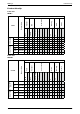
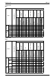
MWM-J_(ii) Product Line-Up Product Line-Up Indoor Unit MWM-J CE A ACLAA X X X X X 15J ACLAA X X X X X 20J ACLAA X X X X X 25J ACLAA X X X X X 09JR ACLAA X X X X X 15JR ACLAA X X X X X 20JR ACLAA X X X X X 25JR ACLAA X X X X X Others Grille Marking Air Purification 09J Bio Filter Saranet Filter PCB LGSN Nomenclature G17 HEATPUMP COOLING MWM Handset Classification Indoor Unit M5WM-J CE ACLAA X X X X X 15J ACLAA X X X X X
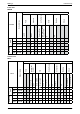
3 Cap Tube 10CJ ACPGG X X X X ACPOG X X X X 15CJ ACPGG X X X X ACPOG X X X X 10CRJ ACPOG X X X X 15CRJ ACPOG X X X X Blue Coated Gold Coated Others Marking Compressor Safety Devices FIN Refrigerant Control PCB ACPOH X X X X 15 C ACPOH X X X X 20C ACPOD X X X X 25C ACPOD X X X X 09CR ACPOH X X X X X 15CR ACPOJ X X X X X 20CR ACPOD X X X X X 25CR ACPOD X X X X X Low Ambient Kit Drain Elbow LP HP Contactor Others Marking Compressor Safety Devices FI
Cap Tube 20CJ ACPOE X X X X X 25CJ ACPOE X X X X X 20CRJ ACPOE X X X X X X 25CRJ ACPOE X X X X X B CE X X X 25J ACLAB X X X X X 20JR ACLAB X X X X X 25JR ACLAB X X X X X Others Saranet Filter X Low Ambient Kit GS01 X Marking Compressor Safety Devices FIN Refrigerant Control PCB ACLAB Bio Filter + Titanium Apatite Filter Others Marking Grille Air Purification Handset PCB Nomenclature LGSN COOLING ONLY 20J Drain Elbow LP HP Contactor Bare Fin Blue C
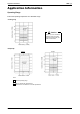
Application Information MWM-J_(ii) Application Information Operating Range Ensure the operating temperature is in allowable range. Outdoor temp. (°CDB) Cooling only 46 Standard point 35 ! Caution : 19 The use of your air conditioner outside the range of working temperature and humidity can result in serious failure. Low ambient kit -5 23 14 Indoor temp. (°CWB) Heatpump Heating Cooling Outdoor temp. (°CDB) Outdoor temp.
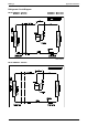
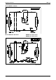
MWM-J_(ii) Application Information Refrigerant Circuit Diagram Model: MWM09J - MLC09C MWM15J - MLC15C M5WM10J - M5LC10CJ M5WM15J - M5LC15CJ 70034 049971 Model: MWM20J - MLC20C 6
Application Information MWM-J_(ii) Model: MWM25J - MLC25C Model: MWM09JR - MLC09CR M5WM10JR - M5LC10CRJ M5WM15JR - M5LC15CRJ 70034 023154 7
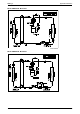
MWM-J_(ii) Application Information Model: MWM15JR - MLC15CR 70034 095236 Model: MWM20JR - MLC20CR 8
Application Information Model: M5WM20J – M5LC20CJ Model: M5WM25J – M5LC25CJ 9 MWM-J_(ii)
MWM-J_(ii) Application Information Model: M5WM20JR – M5LC20CRJ HEATING CAP TUBE CHECK JOINT COOLING & HEATING CAP TUBE CHECK VALVE Model: MWM25JR - MLC25CR CHECK JOINT COOLING & HEATING CAP TUBE 10
Application Information MWM-J_(ii) Model: M5WM25JR – M5LC25CRJ CHECK JOINT COOLING & HEATING CAP TUBE 11
MWM-J_(ii) Application Information Installation Guideline Safety Precautions WARNING CAUTION • Installation and maintenance should be performed by qualified persons who are familiar with local code and regulation, and experienced with this type of appliance. • All field wiring must be installed in accordance with the national wiring regulation. • Ensure that the rated voltage of the unit corresponds to that of the name plate before commencing wiring work according to the wiring diagram.
Application Information MWM-J_(ii) Caution Before installing the unit, ensure that the power supply matches the power requirement of the air conditioner. Installation of Indoor Unit Service Space Install the indoor unit at a location with the following requirements • Location is suitable for wiring, piping and drainage. • No obstruction of air flow into and out of unit where cooler air can be evenly distributed. • Ensure that air discharge is not short circuited with air intake.
MWM-J_(ii) Application Information Cooling Unit (single phase) Indoor Unit Outdoor Unit Terminal Block *** Outdoor coil sensor connection wire Terminal Block (8m long) attached in the indoor unit COMP COMP N1 N N M(5)WM09/10/15J M(5)WM20/25J M(5)LC09/10/15C M(5)LC20/25C Voltage range** 220V-240V/1Ph/50Hz + Power supply cable size* mm2 1.5 2.5 Number of wire 3 3 Interconnection cable size* mm2 1.5 2.
Application Information MWM-J_(ii) Wiring Electrical Connections • Wiring regulations on wire diameters differ from country to country. Please refer to your LOCAL ELECTRICAL CODES for field wiring rules. Be sure that installations comply with the rules and regulations. General Precautions • Ensure that the rated voltage of the unit corresponds to the name plate before carrying out proper wiring according to the wiring diagram. • Provide a power outlet to be used exclusively for each unit.
MWM-J_(ii) Application Information Piping Works • Do not use contaminated or damaged copper tubing. Do not remove plastic, rubber plugs and brass nuts from the valves, fittings, tubings and coils until you are ready to connect suction or liquid line into valves or fittings. • If any brazing work is required, ensure that the nitrogen gas is passed through coil and joints while the brazing work is being done. This will eliminate soot formation on the inside walls of the copper tubings.
Application Information MWM-J_(ii) Vacuuming and Charging The pre-charged outdoor unit does not need any vacuuming or charging. However once it is connected, the connecting pipe line and the indoor unit need to be vacuumed before releasing the R22/R407C/R410A from the outdoor unit. 1. Open the service port core cap. 2. Connect pressure gauge to the service port. 3. Connect the line to vacuum pump. Open the charging manifold valve and turn the pump on. Vacuum to -0.1 MPa (-760mmHg) or lower.
MWM-J_(ii) Application Information Diagram shows typical charging method: (Mclecular-Sieve Type) Note : R22 - Nil R410A - Nil Caution • For R410A, avoid prolong exposure of an opened compressor, or the internal part of refrigerant piping to moist air. The POE oil in the compressor and piping can absorb moisture from air. Overall Checking • Ensure the following, in particular: 1. The unit is mounted solidly and rigid in position. 2. Piping and connections are leak proof after charging. 3.
Application Information MWM-J_(ii) Special Precautions When Dealing With Refrigerant R410A Unit (1) What is new refrigerant R410A? R410A is a new HFC refrigerant which does not damage the ozone layer. The working pressure of this new refrigerant is 1.6 times higher than conventional refrigerant (R22), thus proper installation / servicing is essential.
MWM-J_(ii) Application Information (d) When charging R410A, ensure that only liquid is being withdrawn from the cylinder or can. This is to ensure that only the original composition of R410A is being delivered into the system. The liquid composition can be different from the vapor composition. Dip-pipe Invert cylinder without dip-pipe Liquid withdrawal (e) Normally, the R410A cylinder or can is being equipped with a dip pipe for liquid withdrawal.
Sound Data MWM-J_(ii) Sound Data Sound Pressure Level Speed Model 1k Hz 2k Hz 4k Hz 8k Hz Overall (dBA) High 30 32 33 29 25 19 9 34 28 Medium 27 29 31 27 22 20 11 32 25 (RPM) MWM09J/JR M5WM10J/JR MWM15J/JR M5WM15J/JR MWM20J/JR MWM25J/JR M5WM20J/JR M5WM25J/JR 1/1 Octave Sound Pressure Level (dB, ref 20μPa) 125 Hz 250 Hz 500 Hz Noise Criteria Low 24 26 28 23 19 19 11 29 22 S.
MWM-J_(ii) Sound Data NC Curve MWM09J/JR 60 Sound pressure level (dB,ref20μPa) 50 NC-45 40 NC-40 NC-35 High Fan 30 Medium Fan NC-30 Low Fan NC-25 S.Low Fan 20 NC-20 10 0 125 250 500 1000 2000 4000 8000 Octave-band frequency (Hz) Part Number : 0313103C09 M5WM10J/JR 60 50 Sound pressure level (dB,ref20μPa) NC-45 40 NC-40 NC-35 High Fan 30 NC-30 Medium Fan NC-25 Low Fan 20 NC-20 S.
Sound Data MWM-J_(ii) MWM15J/JR, M5WM15J/JR 60 Sound pressure level (dB, ref20μPa) 50 NC45 40 NC-40 30 High Fan NC-35 Medium Fan NC-30 NC-25 Low Fan 20 NC-20 S.Low Fan 10 0 125 250 500 1000 2000 4000 8000 Octave-band frequency (Hz) Part Number : 0363103C15 MWM20J/JR, M5WM20J/JR 60 Sound pressure level (dB,ref20μPa) 50 NC-45 40 NC-40 NC-35 High Fan 30 NC-30 Medium Fan NC-25 Low Fan 20 NC-20 S.
MWM-J_(ii) Sound Data MWM25J/JR, M5WM25J/JR 60 Sound pressure level (dB,ref20μPa) 50 NC-45 40 NC-40 High Fan NC-35 Medium Fan NC-30 30 NC-25 Low Fan 20 NC-20 S.
Engineering & Physical Data MWM-J_(ii) Engineering & Physical Data Engineering Data - R22 MODEL MODEL INDOOR UNIT MWM09J MWM15J MWM20J MWM25J OUTDOOR UNIT MLC09C MLC15C MLC20C MLC25C Btu/h 8400 12000 19500 24000 W 2460 3520 5720 7030 W 925 1176 5.50 5.40 1850 2530 11.30 NOMINAL COOLING CAPACITY NOMINAL TOTAL INPUT POWER (COOLING) NOMINAL RUNNING CURRENT (COOLING) A EER W/W REFRIGERANT CONTROL (EXPANSION DEVICE) 4.10 2.66 OUTDOOR CAP.
MWM-J_(ii) Engineering & Physical Data Engineering Data - R410A MODEL MODEL INDOOR UNIT M5WM10J M5WM15J M5WM20J M5WM25J OUTDOOR UNIT M5LC10C M5LC15C M5LC20CJ M5LC25CJ Btu/h 9040 10750 17900 20500 W 2650 3150 5250 6010 W 825 1094 1635 1870 NOMINAL COOLING CAPACITY NOMINAL TOTAL INPUT POWER (COOLING) NOMINAL RUNNING CURRENT (COOLING) EER A 3.70 5.10 7.19 W/W 3.21 2.88 3.21 3.21 OUTDOOR OUTDOOR OUTDOOR CAP.
Performance Data MWM-J_(ii) Performance Data Calculation Steps Interpolation method can be used to get the total capacity, TC and sensible capacity, SC and power input, PI at those temperatures which are not stated out in the table. Extrapolation method are not allowed to be used to get the TC, SC and PI Example: Model: MWM09J - MLC09C Indoor Condition: 25°C DB, 17°C WB Outdoor Condition: 37°C DB Fan speed: High Solution: Overall Based on the Performance table: 1.
MWM-J_(ii) Performance Data Details: 1st Step: To obtain the Total capacity, Sensible capacity and Power input for (a) Indoor Condition: 25°C DB, 16°C WB Outdoor Condition: 35°C DB Outdoor DB, ˚C Indoor DB˚C Indoor WB˚C 35 24 16 25 ........................................... 27 TC (kW) SHC (kW) PI (kW) 10.85 10.39 x1 y1 4.00 z1 11.03 11.03 4.01 Total capacity, TC Power Input, PI Interpolation Method: Interpolation Method: 25º C – 24º C 27º C – 24º C = x1 – 10.85kW 11.03kW – 10.
Performance Data MWM-J_(ii) * Repeat process (a) and (b) in 1st step for the condition below: (d) Indoor Condition: 25°C DB, 19°C WB Outdoor Condition: 40°C DB (c) Indoor Condition: 25°C DB, 19°C WB Outdoor Condition: 35°C DB x4= 11.36kW y4= 9.03kW z4= 4.43kW x3= 11.65kW y3= 8.94kW z3= 4.08kW 2nd Step: To obtain the Total capacity, Sensible capacity and Power input for (a) Indoor Condition: 25°C DB, 17°C WB Outdoor Condition: 35°C DB Outdoor DB, ˚C Indoor DB˚C Indoor WB˚C 35 PI (kW) ..
MWM-J_(ii) Performance Data (b) Indoor Condition: 25°C DB, 17°C WB Outdoor Condition: 40°C DB Outdoor DB, ˚C Indoor DB˚C Indoor WB˚C 40 PI (kW) ........ SHC (kW) ........ TC (kW) 10.50 x6 10.37 y6 4.37 z6 18 11.36 9.03 4.43 Total capacity, TC Power Input, PI Interpolation Method: Interpolation Method: 16 17 17º C – 16º C 19º C – 16º C 25 = ........................................... x6 – 10.50kW 11.36kW – 10.50kW 17º C – 16º C 19º C – 16º C = z6 – 4.37kW 4.43kW – 4.
Performance Data MWM-J_(ii) Cooling Only (R22) Model: MWM09J - MLC09C Cooling Mode Outdoor temperature AFR EWB (CFM) EDB 19°C TC 16°C 222 19°C 22°C 16°C 279 19°C 22°C 16°C 335 19°C 22°C SHC 25°C PI TC SHC 30°C PI TC SHC 35°C PI TC PI TC SHC 46°C PI TC SHC PI 21°C 2.32 1.82 0.70 2.24 1.77 0.76 2.16 1.72 0.82 2.07 1.67 0.89 1.90 1.56 0.97 1.75 1.46 1.07 24°C 2.32 2.17 0.70 2.24 2.13 0.76 2.16 2.08 0.82 2.07 2.02 0.89 1.90 1.89 0.97 1.76 1.76 1.07 27°C 2.34 2.34 0.70 2.
MWM-J_(ii) Performance Data Model: MWM15J - MLC15C Cooling Mode Outdoor temperature AFR EWB (CFM) EDB 19°C TC 16°C 240 19°C 22°C 16°C 293 19°C 22°C 16°C 346 19°C 22°C SHC 25°C PI TC SHC 30°C PI TC SHC 35°C PI TC SHC 40°C PI TC SHC 46°C PI TC SHC PI 21°C 3.32 2.38 0.89 3.20 2.31 0.97 3.08 2.25 1.05 2.96 2.19 1.13 2.71 2.04 1.23 2.51 1.92 1.36 24°C 3.32 2.85 0.89 3.20 2.78 0.97 3.08 2.72 1.05 2.96 2.65 1.14 2.72 2.47 1.23 2.52 2.33 1.36 27°C 3.35 3.23 0.90 3.23 3.15 0.
MWM-J_(ii) Performance Data Model: MWM20J - MLC20C Cooling Mode Outdoor temperature AFR EWB (CFM) EDB 19°C TC 16°C 424 19°C 22°C 16°C 478 19°C 22°C 16°C 536 19°C 22°C SHC 25°C PI TC SHC 30°C PI TC SHC 35°C PI TC SHC 40°C PI TC SHC 46°C PI TC SHC PI 21°C 5.39 3.66 1.41 5.20 3.57 1.52 5.01 3.47 1.65 4.80 3.37 1.79 4.41 3.14 1.94 4.07 2.95 2.14 24°C 5.40 4.38 1.41 5.20 4.28 1.52 5.01 4.18 1.65 4.81 4.08 1.79 4.42 3.81 1.94 4.09 3.60 2.14 27°C 5.44 4.97 1.41 5.26 4.86 1.
MWM-J_(ii) Performance Data Model: MWM25J – MLC25C Cooling Mode AFR (CFM) Outdoor temperature EWB 16°C 474 19°C 22°C 16°C 537 19°C 22°C 16°C 646 19°C 22°C EDB 21°C 24°C 27°C 30°C 24°C 27°C 30°C 33°C 27°C 30°C 33°C 36°C 21°C 24°C 27°C 30°C 24°C 27°C 30°C 33°C 27°C 30°C 33°C 36°C 21°C 24°C 27°C 30°C 24°C 27°C 30°C 33°C 27°C 30°C 33°C 36°C TC 6.63 6.64 6.69 6.90 7.31 7.32 7.33 7.41 8.04 8.05 8.05 8.08 6.90 6.92 7.00 7.29 7.60 7.61 7.65 7.77 8.35 8.36 8.37 8.42 7.15 7.19 7.31 7.67 7.87 7.90 7.
Performance Data MWM-J_(ii) Heat Pump (R22) Model: MWM09JR - MLC09CR Cooling Mode Outdoor temperature AFR EWB (CFM) EDB 19°C TC 16°C 222 19°C 22°C 16°C 279 19°C 22°C 16°C 335 19°C 22°C SHC 25°C PI TC SHC 30°C PI TC SHC 35°C PI TC SHC 40°C PI TC SHC 46°C PI TC SHC PI 21°C 2.32 1.82 0.70 2.24 1.77 0.76 2.16 1.72 0.82 2.07 1.67 0.89 1.90 1.56 0.97 1.75 1.46 1.07 24°C 2.32 2.17 0.70 2.24 2.13 0.76 2.16 2.08 0.82 2.07 2.02 0.89 1.90 1.89 0.97 1.76 1.76 1.07 27°C 2.34 2.
MWM-J_(ii) Performance Data Model: MWM09JR – MLC09CR Heating Mode ID DB °C 15 17 19 21 23 25 27 -9 -6 -5 TC SC TC SC TC SC 1.595 1.553 1.511 1.469 1.427 1.386 1.344 1.595 1.553 1.511 1.469 1.427 1.386 1.344 1.805 1.775 1.744 1.701 1.644 1.587 1.530 1.805 1.775 1.744 1.701 1.644 1.587 1.530 1.875 1.828 1.781 1.733 1.686 1.639 1.592 1.875 1.828 1.781 1.733 1.686 1.639 1.592 OUTDOOR WB °C 6 TC SC 2.646 2.642 2.639 2.586 2.482 2.378 2.274 2.646 2.642 2.639 2.586 2.482 2.378 2.
Performance Data MWM-J_(ii) Model: MWM15JR - MLC15CR Cooling Mode Outdoor temperature AFR EWB (CFM) EDB 19°C TC 16°C 240 19°C 22°C 16°C 293 19°C 22°C 16°C 346 19°C 22°C SHC 25°C PI TC SHC 30°C PI TC SHC 35°C PI TC SHC 40°C PI TC SHC 46°C PI TC SHC PI 21°C 3.26 2.34 0.91 3.14 2.28 0.98 3.03 2.21 1.06 2.91 2.15 1.15 2.67 2.00 1.25 2.46 1.88 1.38 24°C 3.26 2.80 0.91 3.15 2.73 0.98 3.03 2.67 1.06 2.91 2.60 1.15 2.67 2.43 1.25 2.47 2.29 1.38 27°C 3.29 3.17 0.91 3.18 3.10 0.
Performance Data MWM-J_(ii) Model: MWM15JR – MLC15CR Heating Mode ID DB °C 15 17 19 21 23 25 27 -9 -6 -5 TC SC TC SC TC SC 2.303 2.243 2.183 2.122 2.062 2.001 1.941 2.303 2.243 2.183 2.122 2.062 2.001 1.941 2.607 2.514 2.421 2.345 2.287 2.229 2.171 2.607 2.514 2.421 2.345 2.287 2.229 2.171 2.708 2.632 2.555 2.478 2.402 2.325 2.248 2.708 2.632 2.555 2.478 2.402 2.325 2.248 OUTDOOR WB °C 6 TC SC 3.821 3.817 3.812 3.708 3.503 3.298 3.093 3.821 3.817 3.812 3.708 3.503 3.298 3.
Performance Data MWM-J_(ii) Model: MWM20JR - MLC20CR Cooling Mode Outdoor temperature AFR EWB (CFM) EDB 19°C TC 16°C 424 19°C 22°C 16°C 478 19°C 22°C 16°C 536 19°C 22°C SHC 25°C PI TC SHC 30°C PI TC SHC 35°C PI TC SHC 40°C PI TC SHC 46°C PI TC SHC PI 21°C 5.39 3.66 1.41 5.20 3.57 1.52 5.01 3.47 1.65 4.80 3.37 1.79 4.41 3.14 1.94 4.07 2.95 2.14 24°C 5.40 4.38 1.41 5.20 4.28 1.52 5.01 4.18 1.65 4.81 4.08 1.79 4.42 3.81 1.94 4.09 3.60 2.14 27°C 5.44 4.97 1.41 5.26 4.86 1.
Performance Data AWM-J_(ii) Model: AWM25JR – ALC25CR Heating Mode ID DB °C 15 17 19 21 23 25 27 TC 3.455 3.364 3.274 3.183 3.093 3.002 2.912 -9 SC TC 3.455 3.364 3.274 3.183 3.093 3.002 2.912 3.910 3.765 3.619 3.517 3.458 3.399 3.340 -6 SC TC 3.910 3.765 3.619 3.517 3.458 3.399 3.340 4.062 3.966 3.869 3.773 3.676 3.580 3.483 -5 SC 4.062 3.966 3.869 3.773 3.676 3.580 3.483 OUTDOOR WB °C 6 TC SC 5.732 5.725 5.719 5.621 5.432 5.244 5.055 5.732 5.725 5.719 5.621 5.432 5.244 5.055 TC 12 6.
MWM-J_(ii) Performance Data Model: MWM25JR – MLC25CR Cooling Mode AFR (CFM) Outdoor temperature EWB 16°C 474 19°C 22°C 16°C 537 19°C 22°C 16°C 646 19°C 22°C EDB 21°C 24°C 27°C 30°C 24°C 27°C 30°C 33°C 27°C 30°C 33°C 36°C 21°C 24°C 27°C 30°C 24°C 27°C 30°C 33°C 27°C 30°C 33°C 36°C 21°C 24°C 27°C 30°C 24°C 27°C 30°C 33°C 27°C 30°C 33°C 36°C TC 6.63 6.64 6.69 6.90 7.31 7.32 7.33 7.41 8.04 8.05 8.05 8.08 6.90 6.92 7.00 7.29 7.60 7.61 7.65 7.77 8.35 8.36 8.37 8.42 7.15 7.19 7.31 7.67 7.87 7.
MWM-J_(ii) Performance Data Model: MWM25JR – MLC25CR Heating Mode ID DB °C 15 17 19 21 23 25 27 -9 -6 -5 TC SC TC SC TC SC 4.429 4.313 4.197 4.081 3.965 3.849 3.733 4.429 4.313 4.197 4.081 3.965 3.849 3.733 5.013 5.470 5.926 5.875 5.314 4.754 4.194 5.013 5.470 5.926 5.875 5.314 4.754 4.194 5.208 5.065 4.921 4.778 4.634 4.491 4.348 5.208 5.065 4.921 4.778 4.634 4.491 4.348 OUTDOOR WB °C 6 TC SC 7.349 7.340 7.331 7.143 6.775 6.407 6.039 7.349 7.340 7.331 7.143 6.775 6.407 6.
Performance Data MWM-J_(ii) Cooling Only (R410A) Model: M5WM10J - M5LC10CJ Cooling Mode Outdoor temperature AFR EWB (CFM) EDB 19°C TC 16°C 222 19°C 22°C 16°C 279 19°C 22°C 16°C 335 19°C 22°C SHC 25°C PI TC SHC 30°C PI TC SHC 35°C PI TC PI TC SHC 46°C PI TC SHC PI 21°C 2.50 1.93 0.63 2.41 1.88 0.68 2.32 1.83 0.73 2.23 1.78 0.80 2.04 1.65 0.86 1.89 1.56 0.95 24°C 2.50 2.31 0.63 2.41 2.26 0.68 2.32 2.21 0.73 2.23 2.15 0.80 2.05 2.01 0.86 1.90 1.90 0.95 27°C 2.52 2.52 0.
MWM-J_(ii) Performance Data Model: M5WM15J - M5LC15CJ Cooling Mode Outdoor temperature AFR EWB (CFM) EDB 19°C TC 16°C 240 19°C 22°C 16°C 293 19°C 22°C 16°C 346 19°C 22°C SHC 25°C PI TC SHC 30°C PI TC SHC 35°C PI TC SHC 40°C PI TC SHC 46°C PI TC SHC PI 21°C 2.97 2.18 0.83 2.86 2.13 0.90 2.76 2.07 0.97 2.65 2.01 1.06 2.43 1.87 1.15 2.24 1.76 1.26 24°C 2.97 2.62 0.83 2.87 2.56 0.90 2.76 2.50 0.97 2.65 2.43 1.06 2.44 2.27 1.15 2.25 2.15 1.26 27°C 3.00 2.97 0.83 2.90 2.
Performance Data MWM-J_(ii) Model: M5WM20J - M5LC20CJ Cooling Mode AFR (CFM) Outdoor temperature EWB 19°C 22°C 16°C 478 19°C 22°C 16°C 536 19°C 22°C 16°C 570 19°C TC 16°C 424 EDB 19°C 22°C SHC 25°C PI TC SHC 30°C PI TC SHC 35°C PI TC SHC TC SHC 46°C PI TC SHC PI 21°C 4.95 3.55 1.24 4.78 3.46 1.34 4.60 3.36 1.46 4.41 3.27 1.58 4.05 3.04 1.71 3.74 2.86 1.89 24°C 4.96 4.25 1.24 4.78 4.15 1.34 4.60 4.06 1.46 4.42 3.96 1.58 4.06 3.69 1.71 3.76 3.49 1.
MWM-J_(ii) Performance Data Model: M5WM25J - M5LC25CJ Cooling Mode AFR (CFM) Outdoor temperature EWB 16°C 474 19°C 22°C 16°C 537 19°C 22°C 16°C 614 19°C 22°C 16°C 641 19°C 22°C EDB 19°C 25°C 30°C 35°C 40°C 46°C TC SHC PI TC SHC PI TC SHC PI TC SHC PI TC SHC PI TC SHC PI 21°C 5.67 3.96 1.42 5.47 3.85 1.54 5.26 3.75 1.66 5.05 3.64 1.80 4.64 3.39 1.96 4.28 3.19 2.16 24°C 5.67 4.74 1.42 5.47 4.63 1.54 5.27 4.52 1.66 5.06 4.41 1.81 4.
Performance Data MWM-J_(ii) Heat Pump (R410A) Model: M5WM10JR - M5LC10CRJ Cooling Mode Outdoor temperature AFR EWB (CFM) EDB 19°C TC 16°C 222 19°C 22°C 16°C 279 19°C 22°C 16°C 335 19°C 22°C SHC 25°C PI TC SHC 30°C PI TC SHC 35°C PI TC PI TC SHC 46°C PI TC SHC PI 21°C 2.50 1.93 0.61 2.41 1.88 0.66 2.32 1.83 0.71 2.23 1.78 0.77 2.04 1.65 0.84 1.89 1.56 0.93 24°C 2.50 2.31 0.61 2.41 2.26 0.66 2.32 2.21 0.71 2.23 2.15 0.77 2.05 2.01 0.84 1.90 1.90 0.93 27°C 2.52 2.52 0.
MWM-J_(ii) Performance Data Model: M5WM10JR - M5LC10CRJ Heating Mode Outdoor WB°C ID DB°C -9 -6 -5 6 12 15 18 TC(kW) SC(kW) TC(kW) SC(kW) TC(kW) SC(kW) TC(kW) SC(kW) TC(kW) SC(kW) TC(kW) SC(kW) TC(kW) SC(kW) 15 1.692 1.692 1.915 1.915 1.989 1.989 2.807 2.807 3.253 3.253 3.476 3.476 3.700 3.700 17 1.648 1.648 1.850 1.850 1.944 1.944 2.804 2.804 3.201 3.201 3.423 3.423 3.645 3.645 19 1.603 1.603 1.785 1.785 1.898 1.898 2.801 2.801 3.149 3.149 3.370 3.370 3.
Performance Data MWM-J_(ii) Model: M5WM15JR - M5LC15CRJ Cooling Mode Outdoor temperature AFR EWB (CFM) EDB 19°C TC 16°C 240 19°C 22°C 16°C 293 19°C 22°C 16°C 346 19°C 22°C SHC 25°C PI TC SHC 30°C PI TC SHC 35°C PI TC PI TC SHC 46°C PI TC SHC PI 21°C 2.97 2.18 0.83 2.86 2.13 0.90 2.76 2.07 0.97 2.65 2.01 1.06 2.43 1.87 1.15 2.24 1.76 1.26 24°C 2.97 2.62 0.83 2.87 2.56 0.90 2.76 2.50 0.97 2.65 2.43 1.06 2.44 2.27 1.15 2.25 2.15 1.26 27°C 3.00 2.97 0.83 2.90 2.90 0.90 2.
MWM-J_(ii) Performance Data Model: M5WM15JR - M5LC15CRJ Heating Mode Outdoor WB°C ID DB°C -9 -6 -5 6 12 15 18 TC(kW) SC(kW) TC(kW) SC(kW) TC(kW) SC(kW) TC(kW) SC(kW) TC(kW) SC(kW) TC(kW) SC(kW) TC(kW) SC(kW) 15 2.043 2.043 2.312 2.312 2.402 2.402 3.389 3.389 3.928 3.928 4.197 4.197 4.467 4.467 17 1.989 1.989 2.255 2.255 2.347 2.347 3.385 3.385 3.869 3.869 4.137 4.137 4.406 4.406 19 1.936 1.936 2.197 2.197 2.293 2.293 3.381 3.381 3.810 3.810 4.078 4.078 4.
Performance Data MWM-J_(ii) Model: M5WM20J - M5LC20CJ Cooling Mode AFR AFR (CFM)” (CFM) EWB EWB 16°C 16°C 424 19°C 19°C 22°C 22°C 16°C 16°C 478 19°C 19°C 22°C 22°C 16°C 16°C 536 19°C 19°C 22°C 22°C 16°C 16°C 570 19°C 19°C EDB EDB 21°C 21°C 24°C 24°C 27°C 27°C 30°C 30°C 24°C 24°C 27°C 27°C 30°C 30°C 33°C 33°C 27°C 27°C 30°C 30°C 33°C 33°C 36°C 36°C 21°C 21°C 24°C 24°C 27°C 27°C 30°C 30°C 24°C 24°C 27°C 27°C 30°C 30°C 33°C 33°C 27°C 27°C 30°C 30°C 33°C 33°C 36°C 36°C 21°C 21°C 24°C 24°C 27°
MWM-J_(ii) Performance Data Model: M5WM20JR - M5LC20CRJ Heating Mode Outdoor WB°C ID DB°C -9 -6 -5 6 12 15 18 Q (kW) SC (kW) Q (kW) SC (kW) Q (kW) SC (kW) Q (kW) SC (kW) Q (kW) SC (kW) Q (kW) SC (kW) Q (kW) SC (kW) 15 3.189 3.189 3.610 3.610 3.750 3.750 5.291 5.291 6.132 6.132 6.553 6.553 6.973 6.973 17 3.106 3.106 3.291 3.291 3.664 3.664 5.285 5.285 6.038 6.038 6.457 6.457 6.876 6.876 19 3.022 3.022 2.973 2.973 3.578 3.578 5.279 5.279 5.944 5.944 6.361 6.
Performance Data MWM-J_(ii) Model: M5WM25J - M5LC25CJ Cooling Mode AFR AFR (CFM) (CFM)” EWB EWB 16°C 16°C 474 474 19°C 19°C 22°C 22°C EDB EDB 19°C 19°C TC PI SHC PI TC TC SHC TC 5.59 21°C 5.67 1.37 5.47 4.05 1.42 5.80 3.96 21°C 5.60 24°C 5.67 1.37 5.47 4.85 1.42 5.81 4.74 24°C 5.66 27°C 1.37 5.50 5.85 27°C 5.72 5.37 1.42 5.53 27°C 6.88 7.04 27°C 30°C 6.88 7.04 30°C 33°C 6.88 7.04 33°C 36°C 6.91 7.07 36°C 4.47 2.17 2.09 4.36 4.77 2.19 2.11 4.66 1.92 1.99 1.92 1.99 4.85 4.74 4.86 4.75 1.92 1.
MWM-J_(ii) Performance Data Model: M5WM25JR - M5LC25CRJ Heating Mode Outdoor WB°C ID DB°C -9 -6 -5 6 12 15 18 Q (kW) SC (kW) Q (kW) SC (kW) Q (kW) SC (kW) Q (kW) SC (kW) Q (kW) SC (kW) Q (kW) SC (kW) Q (kW) SC (kW) 15 3z.721 3.721 4.211 4.211 4.375 4.375 6.173 6.173 7.154 7.154 7.645 7.645 8.135 8.135 17 3.623 3.623 3.734 3.734 4.282 4.282 6.166 6.166 7.081 7.081 7.575 7.575 8.069 8.069 19 3.526 3.526 3.257 3.257 4.189 4.189 6.158 6.158 7.008 7.008 7.
Outline & Dimension MWM-J_(ii) Outline & Dimension Indoor Unit Model: MWM09/15J/JR, M5WM10/15J/JR 206 288 800 50123456789 Note: Dimension in mm Outdoor Unit Model: MLC09/15C/CR, M5LC10/15C/CR CJ / CRJ K L N 30 (1.2) C M N L C G H F D 19 (0.7) 80 65 (3.1) (2.6) B E 3 (0.1) A O Dimension 10 // 15 CJ / /CRJ 10 15C CR I A B C D E F G H I J K L M N O 700 521 250 485 175 36 95 93 86 68 441 130 111 15 18 (27.5) (20.5) (9.8) (19.1) (6.8) (1.4) (3.
MWM-J_(ii) Outline & Dimension Indoor Unit Model: M(5)WM20/25J/JR Note: Dimension in mm Outdoor Unit Model: M(5)LC20/25CJ/CRJ For M5LC / MLC25C/CR Note : Dimension in mm MODEL A B C D E F G H I J K L M N O P Q R S T M(5)LC20CJ/CRJ 855 628 328 508 181 44 93 149 101 113 603 126 164 17 49 32 3 23 73 75 M(5)LC25CJ/CRJ 855 730 328 513 182 44 93 149 101 113 603 126 164 17 47 32 3 23 73 75 Note: Dimension in mm 56
Wiring Diagram MWM-J_(ii) Wiring Diagram Cooling Only Indoor Unit Model: MWM09/15J M5WM10/15J Outdoor Unit Model: MLC09/15CJ M5LC10/15CJ 70034 101945 57
MWM-J_(ii) Wiring Diagram Cooling Only Indoor Unit Model: MWM20/25J Outdoor Unit Model: MLC20/25C 70034 108883 58
Wiring Diagram MWM-J_(ii) Heat Pump Indoor Unit Model: MWM09/15JR M5WM10/15JR Outdoor Unit Model: MLC09/15CRJ M5LC10/15CRJ 70034 101944 59
MWM-J_(ii) Wiring Diagram Heat Pump Indoor Unit Model: MWM20/25JR Outdoor Unit Model: MLC20/25CR 70034 108882 60
Wiring Diagram MWM-J_(ii) Cooling Only Indoor Unit Model: M5WM20/25J Outdoor Unit Model: M5LC20/25CJ 70034 108883 61
MWM-J_(ii) Wiring Diagram Heat Pump Indoor Unit Model: M5WM20/25JR Outdoor Unit Model: M5LC20/25CRJ 70034 108882 62
Service & Maintenance MWM-J_(ii) Service & Maintenance Warning • Disconnect from main supply before servicing the air conditioner. • The unit is designed to give long life operation with minimum maintenance required. However, it should be regularly checked and the following items should be given due attention. Components Maintenance Procedures Period Air Filter (Indoor Unit) 1.
MWM-J_(ii) Service & Maintenance Pre Start Up Maintenance (After Extended Shutdown) • • • • • • • Inspect thoroughly and clean indoor and outdoor units. Clean or replace air filters. Clean condensates drain line. Clean clogged indoor and outdoor coils. Check fan imbalance before operation. Tighten all wiring connections and panels. Check for refrigerant leakage. Outdoor Models The design of the A5LC outdoor series allows servicing to be carried out easily.
Troubleshooting MWM-J_(ii) Troubleshooting Indicator Lights IR Signal Receiver When an infra red remote control operating signal has been transmitted, the signal receiver on the indoor unit will respond as below to confirm acceptance of the signal transmission. ON to OFF 1 Long Beep OFF to ON Pump down/Cool force on 2 Short Beep Others 1 Short Beep Cooling Unit / Heat Pump Unit The table below shows the LED indicator lights for the air conditioner unit under normal operation and fault conditions.
MWM-J_(ii) Troubleshooting LED Indoor Lights: Normal Operation and Fault Conditions for Cooling / Heat Pump Unit 1 COOL/HEAT (GREEN/RED) Green Red Red Green Error Code Normal Operation / Fault Indication Action - Cool mode - - Heat mode - - Auto mode in Heating operation - - Auto mode in Cooling operation - - Time on - - Sleep mode on - - Fan mode on - - Dry mode on - Room air sensor contact loose / short Check room sensor connection / change room air sensor 1 time Blink
Troubleshooting MWM-J_(ii) Error Code / Fault Condition When a malfunction of the air conditioner unit is detected, immediately switch off the main power supply before proceeding with the following troubleshooting procedures. The following are common fault conditions and simple troubleshooting tips. If any other fault conditions which are not listed occur, contact your nearest local dealer. DO NOT attempt to troubleshoot the unit by yourself.
MWM-J_(ii) Troubleshooting Diagnostic Guidelines By means of pressure readings: • • High side Low side High side Low side High side Low side High side Low side High side Low side • • Probable cause Too high A little high Normal Too low Circuit Pressure A little low Data • • 1. 2. 3. 4. Overcharged with refrigerant. Non-condensable gases in refrigerant circuit (e.g. air). Obstructed air-intake / discharge. Hot air short circuiting in outdoor unit. 1.
Exploded View & Part List MWM-J_(ii) Exploded View & Part List INDOOR UNIT MODEL: MWM09/15J/JR, M5WM10/15J/JR 16 13 15 8 14 11 12 18 4 10 3 9 1 17 7 22 5 6 2 21 20 19 70024102581 Note: All exploded view and part list are subjected to change by the manufacturer without prior notice 69
MWM-J_(ii) Exploded View & Part List INDOOR UNIT MODEL: MWM09/15J/JR, M5WM10/15J/JR No Description No Description 1 Assy. Front Grille 13 Right Side Panel 2 Panel, McQuay 14 Cover, Drip Proof 3 Disch. Grille Hor.Blade Assy. 15 Clip, Coil Sensor 4 Assy. Bottom Frame 16 Assy. Heat Exchanger 5 Assy. Control Box 17 Assy. Drain Hose 6 Assy. Service Cover 18 Fan Bearing Vibration Absorber 7 Assy.
Exploded View & Part List MWM-J_(ii) INDOOR UNIT MODEL: MWM20/25J/JR No Description No Description 1 Assy, Chassis 11 Assy, PCB (with Lamp Cover) 2 Motor 12 Control Box Cover 3 Blower 13 Service Cover 4 Fan Bush 14 Assy, Mounting Plate 5 Motor Cover 15 Assy, Front Cover 6 Assy, Indoor Coil 16 Front Cover 7 Assy, Air Discharge Housing 17 Intake Grill 8 Assy, Louver 18 Filter 9 Hose 19 Handset Wireless 10 Assy, Control Box Note: All exploded view and part list are
MWM-J_(ii) Exploded View & Part List INDOOR UNIT MODEL: M5WM20/25J/JR No Description No Description 1 Assy, Chassis WM20/25J 11 Assy. PCB (with Lamp Cover) 2 Motor 12 Control Box Cover 3 Blower 13 Service Cover 4 Fan Bush 14 Assy. Mounting Plate 5 Motor Cover 15 Assy. Front Cover 6 Assy. Indoor Coil 16 Front Cover 7 Assy. Air Discharge Housing 17 Intake Grill 8 Assy. Louver 18 Filter 9 Hose 19 Handset Wireless 10 Assy.
Exploded View & Part List MWM-J_(ii) OUTDOOR UNIT MODEL: MLC09C 70024056770 No Description No Description 1 Assy. Base Pan 13 Assy. Control Panel 2 Assy. Outdoor Coil 14 Assy. Valve Cover 3 Valve Bracket 15 Assy. Front Grille 4 Compressor 16 Plastic Handle 5 Assy. Partition 17 Rubber Grommet 6 Assy. Cap Tube 18 7 Bracket, Fan Motor Assy. Flare Valve 2 Ways 1/4” 8 Fan Motor 19 Assy. Flare Valve 3 Ways 3/8” 9 Fan Blade 10 Left Panel 11 Right Panel 12 Assy.
MWM-J_(ii) Exploded View & Part List OUTDOOR UNIT CJ MODEL: MLC15C, M5LC10/15C 70024056771 No Description No Description 1 Assy. Base Pan 13 Assy. Control Panel 2 Assy. Outdoor Coil 14 Assy. Valve Cover 3 Valve Bracket 15 Assy. Front Grille 4 Compressor 16 Plastic Handle 5 Assy. Partition 17 Rubber Grommet 6 Assy. Cap Tube 18 Assy. Flare Valve 2 Ways 1/4” 7 Bracket, Fan Motor 19 Assy.
Exploded View & Part List MWM-J_(ii) OUTDOOR UNIT MODEL: MLC09CR 70024061683 Note: All exploded view and part list are subjected to change by the manufacturer without prior notice 75
MWM-J_(ii) Exploded View & Part List OUTDOOR UNIT MODEL: MLC09CR No Description No Description 1 Assy. Base Pan 14 Assy. Control Panel 2 Assy. Outdoor Coil 15 Assy. Valve Cover 3 Valve Bracket 16 Assy. Front Grille 4 Compressor 17 Plastic Handle 5 Assy. Partition 18 Rubber Grommet 6 Assy. 4 Way Valve 19 7 Assy. Cap Tube Assy. Flare Valve 2 Ways 1/4” 8 Bracket, Fan Motor 20 Assy.
Exploded View & Part List MWM-J_(ii) OUTDOOR UNIT CRJ MODEL: MLC15CR, M5LC10/15CR 70024061687 Description No Description 1 Assy. Base Pan 14 Assy. Control Panel 2 Assy. Outdoor Coil 15 Assy. Valve Cover 3 Valve Bracket 16 Assy. Front Grille 4 Compressor 17 Plastic Handle 5 Assy. Partition 18 Rubber Grommet 6 Assy. 4 Way Valve 19 Assy. Flare Valve 2 Ways 1/4” 7 Assy. Cap Tube 20 Assy.
MWM-J_(ii) Exploded View & Part List OUTDOOR UNIT MODEL: MLC20C/CR Note: All exploded view and part list are subjected to change by the manufacturer without prior notice 78
Exploded View & Part List MWM-J_(ii) OUTDOOR UNIT MODEL: MLC20C No Description No Description 1 Assy. Base Pan 13 Top Panel 2 Assy. Outdoor Coil 14 Assy. Front Grille 3 Bracket, Fan Motor 15 Plastic Handle 4 Fan Motor 16 Assy. Valve Cover 5 Fan Propeller 17 Assy. Cap Tube 6 Assy. Valve Bracket 18 Partition 7 Back Panel, Right 8 Compressor Capacitor, Fan Motor 9 Front Panel, Left Capacitor, Compressor 10 Service Panel Assy.
MWM-J_(ii) Exploded View & Part List OUTDOOR UNIT MODEL: MLC25C/CR Note: All exploded view and part list are subjected to change by the manufacturer without prior notice 80
Exploded View & Part List MWM-J_(ii) OUTDOOR UNIT MODEL: MLC25C No Description No Description 1 Assy. Base Pan 13 Top Panel 2 Assy. Outdoor Coil 14 Assy. Front Grille 3 Bracket, Fan Motor 15 Plastic Handle 4 Fan Motor 16 Assy. Valve Cover 5 Fan Propeller 17 Assy. Cap Tube 6 Assy. Valve Bracket 18 Partition 7 Back Panel, Right 8 Compressor Capacitor, Fan Motor Assy. Compressor Capacitor, Compressor 9 Front Panel, Left Assy.
MWM-J_(ii) Exploded View & Part List OUTDOOR UNIT MODEL: M5LC20CJ/CRJ Note: All exploded view and part list are subjected to change by the manufacturer without prior notice 82
Exploded View & Part List MWM-J_(ii) OUTDOOR UNIT MODEL: M5LC20CJ No Description No Description 1 Assy. Base Pan 13 Top Panel 2 Assy. Outdoor Coil 14 Assy. Front Grille 3 Bracket, Fan Motor 15 Plastic Handle 4 Fan Motor 16 Assy. Valve Cover 5 Fan Propeller 17 Assy. Cap Tube 6 Assy. Valve Bracket 18 Partition 7 Back Panel, Right 8 Compressor Capacitor, Fan Motor 9 Panel Front Left Capacitor, Compressor 10 Service Panel Assy.
MWM-J_(ii) Exploded View & Part List OUTDOOR UNIT MODEL: M5LC25CJ No Description No Description 1 Assy. Base Pan 11 Plastic, Handle 2 Assy. Outdoor Coil 12 Assy. Compressor 3 Bracket, Motor 13 Suction Tube 4 Assy. Valve Bracket 14 Discharge Tube 5 Panel, Partition 15 Compressor Felt 6 Assy. Valve Cover 16 Assy. Control Box 7 Motor 17 Service Panel 8 Fan Propeller 18 Assy. Panel Top 9 Assy.
Exploded View & Part List MWM-J_(ii) OUTDOOR UNIT MODEL: M5LC25CRJ No Description No Description 1 Assy. Base Pan 11 Panel, Right Back 2 Assy. Outdoor Coil 12 Panel, Service 3 Bracket, Motor 13 Assy. Panel Top 4 Assy. Valve Bracket 14 Motor 5 Panel, Partition 15 Fan Propeller 6 Assy. Valve Cover 16 Assy. Compressor 7 Assy. Panel Front Left 17 Assy. Tubing 4WV 8 Plastic, Handle 18 Compressor Felt 9 Plastic, Front Grille 19 Assy. Control Box 10 Assy.
Products manufactured in an ISO certified facility. This document contains the most current product information as of this printing. For the most up-to-date product information, please go to www.mcquayup.com. © 2011 McQuay International www.mcquayup.
Revision History List Manual Revision : Wall Mounted Split System Subject TM : MWM-J_(ii) Amendment on Manual’s Page No. Date 26 20.10.2011 14.12.2011 01 1. Correction on Refrigerant Charge 02 1. Correction on Engineering Data 25, 26 1. Correction on Engineering Data 25 03 22.2.2012 2.