
Technical data


OM 1191 85
Technical Data
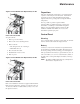
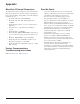
WARNING
Relay coils generate noise spikes in response to steps
in applied power. To avoid drive damage from such
spikes, all AC relay coils mounted across drive inputs
require R-C snubbers, and all DC relay coils mounted
across drive outputs require diodes – see figure.
Analog Cables
Recommendations for analog signal runs:
• Use double shielded, twisted pair cable.
• Use one individually shielded pair for each signal.
• Do not use a common return for different analog signals.
Digital Cables
Recommendation for digital signal runs: A double shielded
cable is the best alternative, but single-shielded, twisted,
multi-pair cable is also usable.
Control Panel Cable
If the control panel is connected to the drive with a cable, use
only Category 5 Patch ethernet cable.
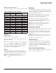
Drive’s Control Connection Terminals
Thefollowingtableprovidesspecicationsforthedrive’s
control terminals
Frame Size
Control
Maximum Wire Size Torque
mm2 AWG Nm lb-ft
All
1.5 16 0.4 0.3
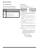
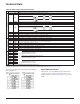
Control Terminal Descriptions
The following full-page diagram provides a general
descriptionofthecontrolterminalsonthedrive.Forspecic
application details, see the ApplicationMacrosonpage9.
NOTE: Terminals 3, 6, and 9 are at the same potential.
For safety reasons the fault relay signals a “fault”
when the MD5 is powered down.