
Technical data


84 OM 1191
Technical Data
Control connections
Control Connection Specications
Table 59: Control Connection Specications
Analog
Inputs and
Outputs
See Table 60: Drive Control Terminal Descriptions on page
86.
Digital
Inputs
Digital input impedance 1.5 kΩ. Maximum voltage for digital
inputs is 30 V.
Relays
(Digital
Outputs)
• Max. contact voltage: 30 V DC, 250 V AC
• Max. contact current / power: 6 A, 30 V DC; 1500 VA, 250 V
AC
• Max. continuous current: 2 A rms (cos ϕ = 1),
1 A rms (cos ϕ
= 0.4)
• Minimum load: 500 mW (12 V, 10 mA)
• Contact material: Silver-nickel (AgN)|
• Isolation between relay digital outputs, test voltage: 2.5 kV
rms, 1 minute
Control Cables
General Recommendations
Use multi-core cables with a braided copper wire screen,
temperature rated at 60 °C (140 °F) or above:
At the drive end, twist the screen together into a bundle not
longerthanvetimesitswidthandconnectedtoterminal
X1-1 (for digital and analog I/O cables) or to either X1-28 or
X1-32 (for RS485 cables).
Route control cables to minimize radiation to the cable:
• Route as far away as possible from the input power and
motor cables (recommend at least 20 cm [8 in] where
practical).
• Where control cables must cross power cables make sure
theyareatanangleasnear90°aspossible.
• Stay at least 20 cm (8 in) from the sides of the drive
where practical.
Use care in mixing signal types on the same cable:
• Do not mix analog and digital input signals on the same
cable.
• Run relay-controlled signals as twisted pairs (especially
if voltage > 48 V). Relaycontrolled signals using less
than 48 V can be run in the same cables as digital input
signals.
NOTE: Never mix 24 VDC and 115/230 VAC signals in the
same cable.
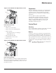
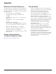
Triacs used as sources for drive inputs, may have
excessive leakage current in the OFF state, enough
to read as ON to drive inputs. Driving two or more
inputs, divides the leakage current, reducing or
eliminating the problem. An alternative is to add a
small capacitive load – see gure.