
Technical data


OM 1191 81
Maintenance
Maintenance
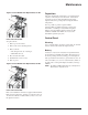
Figure 12: Drive Module Fan Replacement, R1–R4
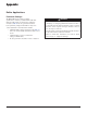
Frame Sizes R5 and R6
To replace the fan:
1. Remove power from drive.
2. Remove the screws attaching the fan.
3. Remove the fan:
— R5: Swing the fan out on its hinges.
— R6: Pull the fan out.
4. Disconnect the fan cable.
5. Install the fan in reverse order.
6. Restore power.
Figure 13: Drive Module Fan Replacement, R5–R6
Frame Sizes R7 and R8
Refer to the installation instructions supplied with the fan kit.
Enclosure fan replacement – UL Type 12 enclosures UL type
12 enclosures include an additional fan (or fans) to move air
through the enclosure.
Capacitors
The drive intermediate circuit employs several electrolytic
capacitors.Theirlifespanisfrom35,000…90,000hours
depending on drive loading and ambient temperature.
Capacitor life can be prolonged by lowering the ambient
temperature.
It is not possible to predict a capacitor failure.
Capacitor failure is usually followed by a input power
fuse failure or a fault trip. Contact Daikin if capacitor
failure is suspected. Replacements for frame size R5
and R6 are available from Daikin. Do not use other
than Daikinspecifiedspareparts.
Control Panel
Cleaning
Use a soft damp cloth to clean the control panel. Avoid harsh
cleaners which could scratch the display window.
Battery
A battery is only used in Assistant control panels that have
the clock function available and enabled. The battery keeps
the clock operating in memory during power interruptions.
The expected life for the battery is greater than ten years. To
remove the battery, use a coin to rotate the battery holder on
the back of the control panel. Replace the battery with type
CR2032.
NOTE: The battery is NOT required for any control panel or
drive function, except the clock.