
Technical data


OM 1191 71
Fieldbus Adapter
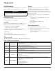
PID Control Setpoint Source
UsingtheeldbusforthePIDcontrolsetpointrequires: • Driveparametervaluessetasdenedbelow.
• Fieldbus controller supplied setpoint value in the
appropriatelocation.(AsdenedinAnalogoutput
control above.)
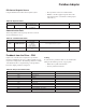
Table 48: Setpoint Values
Drive Parameter Value Description Protocol Reference
4010 SETPOINT SEL
8 (COMM VALUE 1)
9 (COMM + AI1)
10 (COMM*AI1)
Setpoint is 0135 value (+/-/* AI1) —
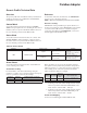
Communication Fault
Whenusingeldbuscontrol,specifythedrive’sactionif
serial communication is lost.
Table 49: Communication Fault
Drive Parameter Value Description Protocol Reference
3018 COMM FAULT FUNC
0 (NOT SEL)
1 (FAULT)
2 (CONST SP7)
3 (LAST SPEED)
Set for appropriate drive response. —
3019 COMM FAULT TIME
Set time delay before
acting on a communication
loss.
–
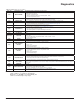
Feedback from the Drive – FBA
Inputstothecontroller(driveoutputs)havepre-dened
meanings established by the protocol. This feedback does not
requiredriveconguration.Thefollowingtablelistsasample
of feedback data. For a complete listing, see all parameters
listed in Complete parameter descriptions.
Scaling
To scale the drive parameter values see the Actual value
scaling in the following sections, as appropriate:
•
Daikindrivesprofiletechnicaldata
• Genericproletechnicaldata
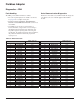
Table 50: Sample of Feedback Data
Drive Parameter Protocol Reference
0102 SPEED
0103 FREQ OUTPUT
0104 CURRENT
0105 TORQUE
0106 POWER
0107 DC BUS VOLT
0109 OUTPUT VOLTAGE
0301 FB STATUS WORD – bit 0 (STOP)
0301 FB STATUS WORD – bit 2 (REV)
0118 DI1-3 STATUS – bit 1 (DI3)