
Technical data


OM 1191 39
Parameters
Group 64: Load Analyzer
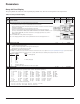
Thisgroupdenestheloadanalyzer,whichcanbeusedforanalyzingthecustomer’sprocessandsizingthedriveandthemotor.
The peak value is logged at 2 ms level, and the distribution loggers are updated on 0.2 s (200 ms) time level. Three different
values can be logged.
1. Amplitude logger 1: The measured current is logged continuously. The distribution as a percentage of the nominal current
I2
n
is shown in ten classes.
2. Peak value logger: One signal in group 1 can be logged for the peak (maximum) value. The peak value of the signal, peak
time (time when the peak value was detected) as well the frequency, current and DC voltage at the peak time are shown.
3. Amplitude logger 2: One signal in group 1 can be logged for amplitude distribution. The base value (100% value) can be
set by the user.
Therstloggercannotbereset.Theothertwologgerscanberesetbyauserdenedmethod.Theyarealsoresetifeitherofthe
signalsorthepeakvalueltertimeischanged.
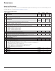
Table 21: Group 64: Load Analyzer
Code Description Range Resolution Default S
6401 PVL SIGNAL 100…178 1
103
(OUTPUT
FREQ)
Denes (by number) the signal logged for the peak value.
• Any parameter number in Group 01: Operating Data on page 13
can be selected. Eg 102 = parameter 0102 SPEED.
100 = NOT SELECTED – No signal (parameter) logged for the peak value.
101…178 – Logs parameter 0101…0178.
6402 PVL FILTER TIME
0.0…120.0 s 0.1 s 0.1 s
Denes the lter time for peak value logging.
• 0.0…120.0 – Filter time (seconds).
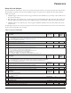
6403 LOGGERS RESET -6…7 1
0
(NOT SEL)
Denes the source for the reset of peak value logger and amplitude logger 2.
0 = NOT SEL – No reset selected.
1 = DI1 – Reset loggers on the rising edge of digital input DI1.
2…6 = DI2…DI6 – Reset loggers on the rising edge of digital input DI2…DI6.
7 = RESET – Reset loggers. Parameter is set to NOT SEL.
-1 = DI1(INV) – Reset loggers on the falling edge of digital input DI1.
-2…-6 = DI2(INV) …DI6(INV) – Reset loggers on the falling edge of digital input DI2…DI6.
6404 AL2 SIGNAL 101…178 1
103
(OUTPUT
FREQ)
Denes the signal logged for amplitude logger 2.
• Any parameter number in Group 01: Operating Data
can be selected. Eg 102 = parameter 0102 SPEED.
100 = NOT SELECTED – No signal (parameter) logged for amplitude distribution (amplitude logger 2).
101…178 – Logs parameter 0101…0178.
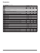
6405 AL2 SIGNAL BASE
Depends on
selection
—
60.0 Hz
Denes the base value from which the percentage distribution is calculated.
• Representation and default value depends on the signal selected with parameter 6404 AL2 SIGNAL.
6406 PEAK VALUE — — —
Detected peak value of the signal selected with parameter 6401 PVL SIGNAL.
6407 PEAK TIME 1
Date dd.mm.yy
/ power-on time
in days
1 d —
Date of the peak value detection.
• Format: Date if the real time clock is operating (dd.mm.yy). / The number of days elapsed after the power-on if the real time clock is not used,
or was not set (xx d).
6408 PEAK TIME 2 Time hh.mm.ss 2 s —
Time of the peak value detection.
• Format: hours:minutes:seconds.
6409 CURRENT AT PEAK
0.0…6553.5 A 0.1 A —
Current at the moment of the peak value (amperes).
6410 UDC AT PEAK 0…65535 V 1 V —
DC voltage at the moment of the peak value (volts).